Determination of mechanical shutter exposure time

a technology of mechanical shutter and exposure time, which is applied in the direction of exposure control, instruments, television systems, etc., can solve the problems of not being able to perfectly match the exposure time, the property of the rolling shutter, and the inability to set the exposure time very accurately

a technology of mechanical shutter and exposure time, which is applied in the direction of exposure control, instruments, television systems, etc., can solve the problems of not being able to perfectly match the exposure time, the property of the rolling shutter, and the inability to set the exposure time very accurately

US7724301B2Inactive Publication Date: 2010-05-25NOKIA TECH OY

Image

  • Determination of mechanical shutter exposure time
  • Determination of mechanical shutter exposure time
  • Determination of mechanical shutter exposure time

Examples


Embodiment Construction

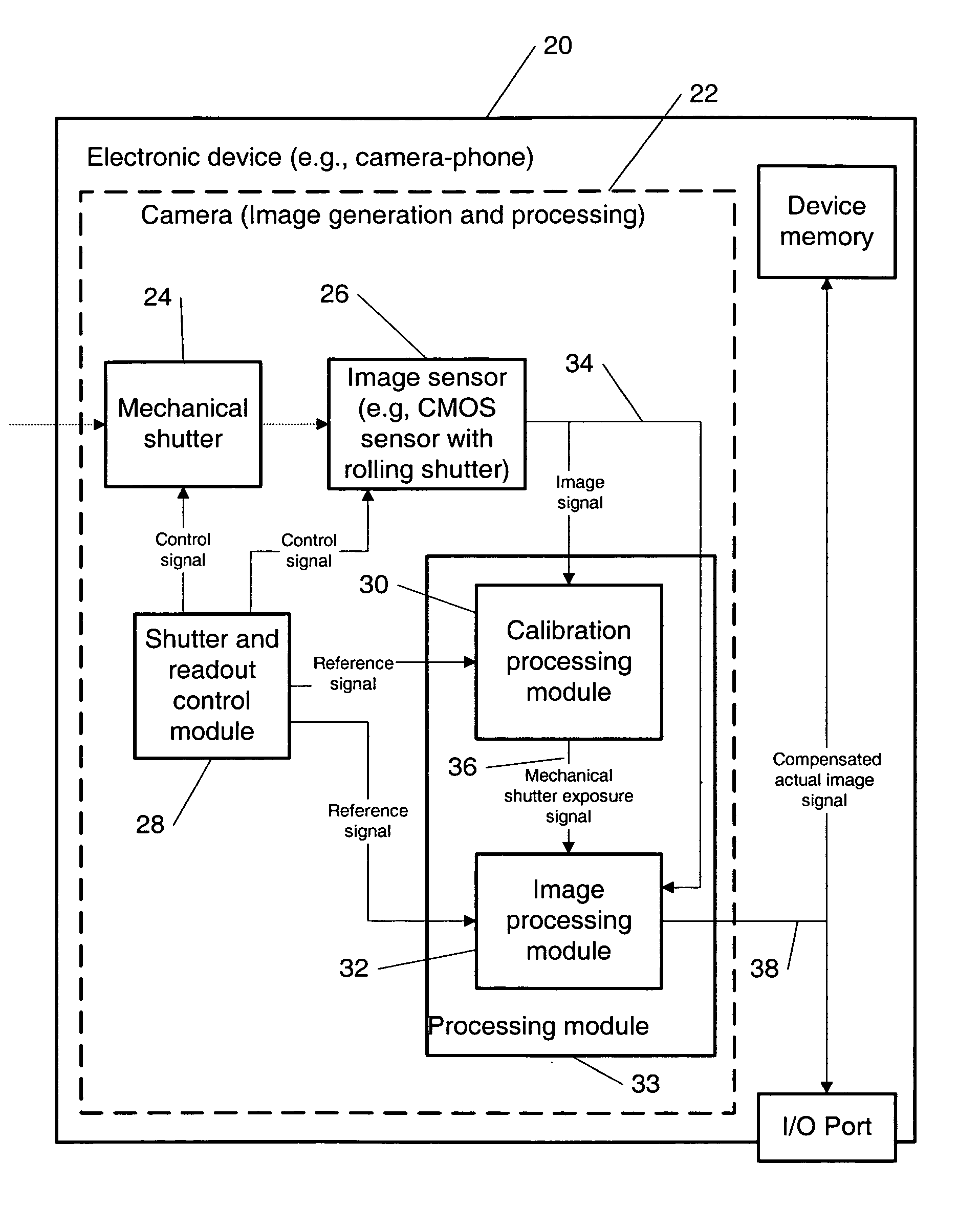
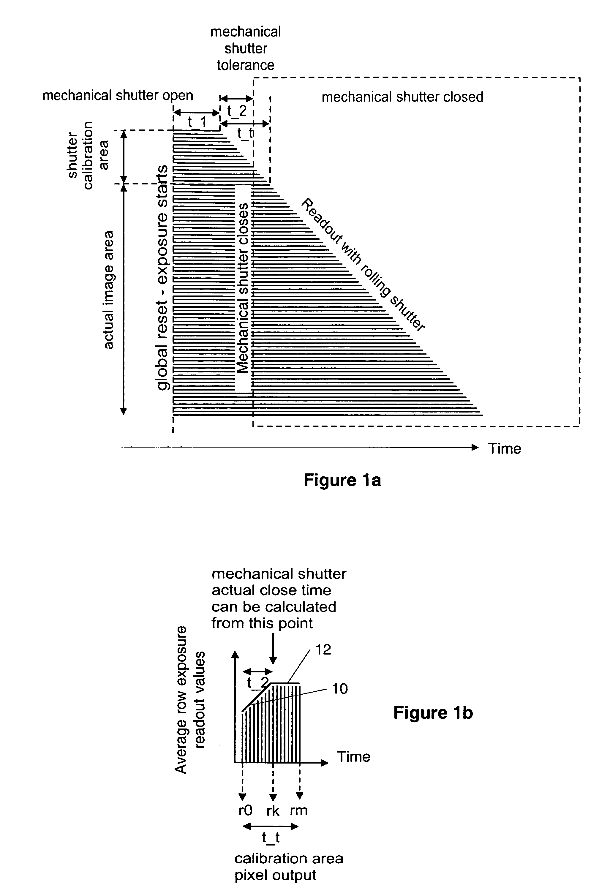
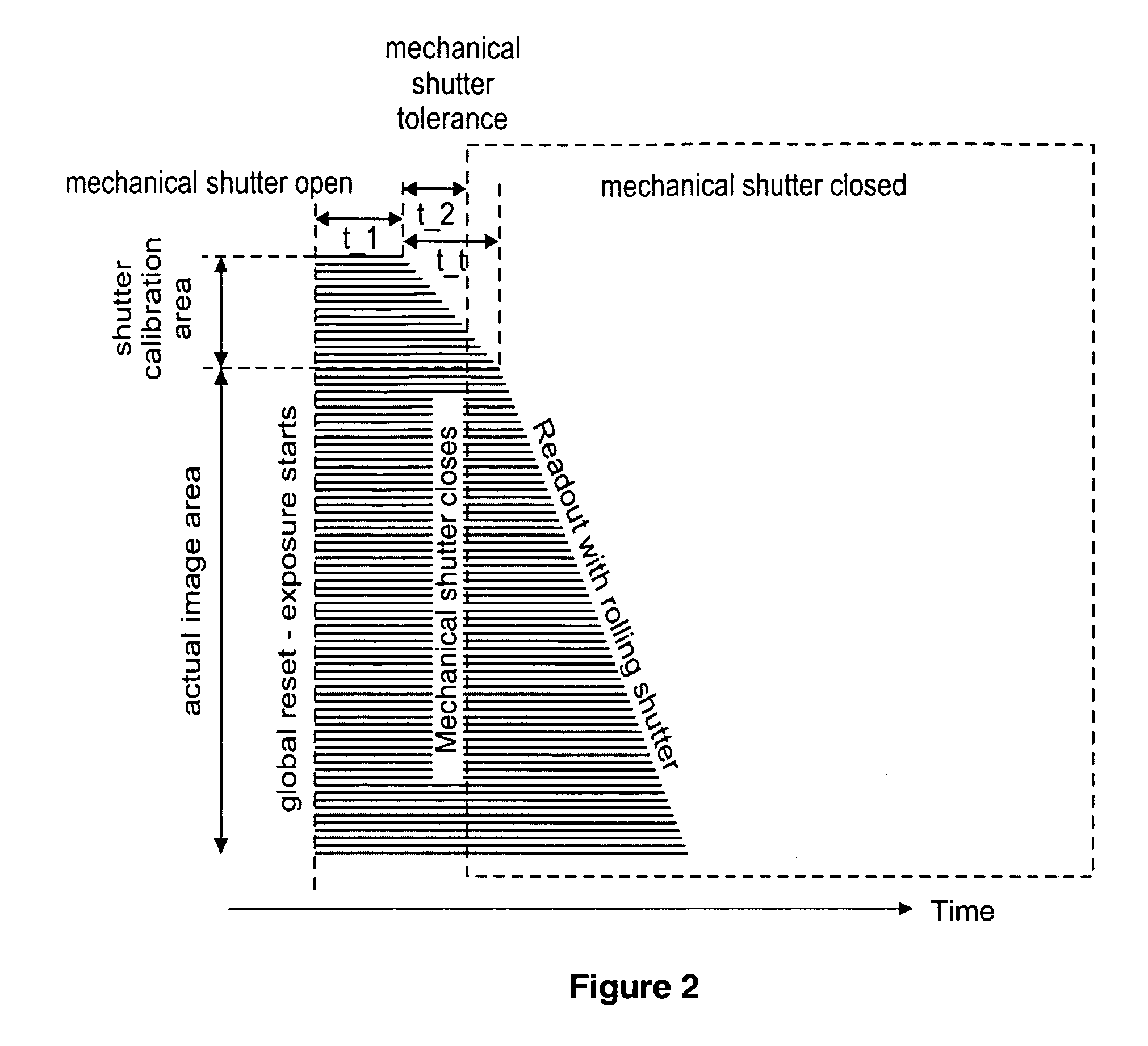
[0044]A new method, apparatus and software product for determining a mechanical shutter exposure time (e.g., an actual closing time) with a rolling readout of an image (e.g., complimentary metal oxide semiconductor, CMOS) sensor using a predetermined calibration area of the image sensor in digital cameras or in electronic devices with digital cameras.

[0045]According to embodiments of the present invention, in a digital camera with the image sensor (e.g., the CMOS sensor), a predefined exposure of an image on the image sensor with a rolling shutter capability can be provided using a mechanical shutter, wherein said predefined exposure is defined by a global reset time (at which time the mechanical shutter is open) and a closing time of the mechanical shutter. An image signal comprising calibration and actual image signals can be provided by a rolling readout of said image in response to said predefined exposure using the image sensor, wherein the calibration image signal is provided ...


PUM


Abstract

The specification and drawings present a new method, apparatus and software product for determining a mechanical shutter exposure time (e.g., an actual closing time) with a rolling readout of an image (e.g., complimentary metal oxide semiconductor) sensor using a predetermined calibration area of the image sensor in digital cameras or in electronic devices with digital cameras.

Description

TECHNICAL FIELD[0001]The present invention relates generally to electronic devices with digital cameras and more specifically, to digital cameras or electronic device with digital cameras that use a mechanical shutter and an image sensor with a rolling readout.BACKGROUND ART[0002]An image sensor is a component that converts a visible image to an electric signal in a camera (e.g., a digital camera). The image sensors can be divided into two categories: CMOS (complimentary metal oxide semiconductor) or CCD (charge coupled device) sensors. CMOS sensors are used commonly in mobile phones due to their higher degree of integration, lower price and lower power consumption.[0003]One of the biggest problems in a CMOS sensor is its property called a rolling shutter. If a sensor has the rolling shutter, it is exposed line by line, instead of globally. Since each line is exposed at a slightly different time moment, images of moving targets seem to bend. This bending is called a motion skew.[000...

Claims


Application Information

Patent Timeline
25 May 2010
Publication
US7724301B2
IPC
G03B7/00; H04N5/235
CPC
G03B43/02; H04N5/2254; H04N5/3532; H04N5/2353; H04N5/2352; H04N23/72; H04N23/73; H04N25/531
Inventors
ALAKARHU, JUHA