Method and apparatus for visualizing anatomical structures

a technology of anatomical structures and visualization methods, applied in the field of medical systems, to achieve the effect of good images of the bone structure of patients

Active Publication Date: 2010-05-25
ASTUTE IMAGING LLC
View PDF8 Cites 110 Cited by
  • Summary
  • Abstract
  • Description
  • Claims
  • Application Information

AI Technical Summary

Problems solved by technology

While effective, the foregoing process requires the generation of multiple images, the use of a contrast agent which may be deleterious to the patient's health, the processing associated with image subtraction, etc.

Method used


Image

  • Method and apparatus for visualizing anatomical structures
  • Method and apparatus for visualizing anatomical structures
  • Method and apparatus for visualizing anatomical structures

Examples


Embodiment Construction

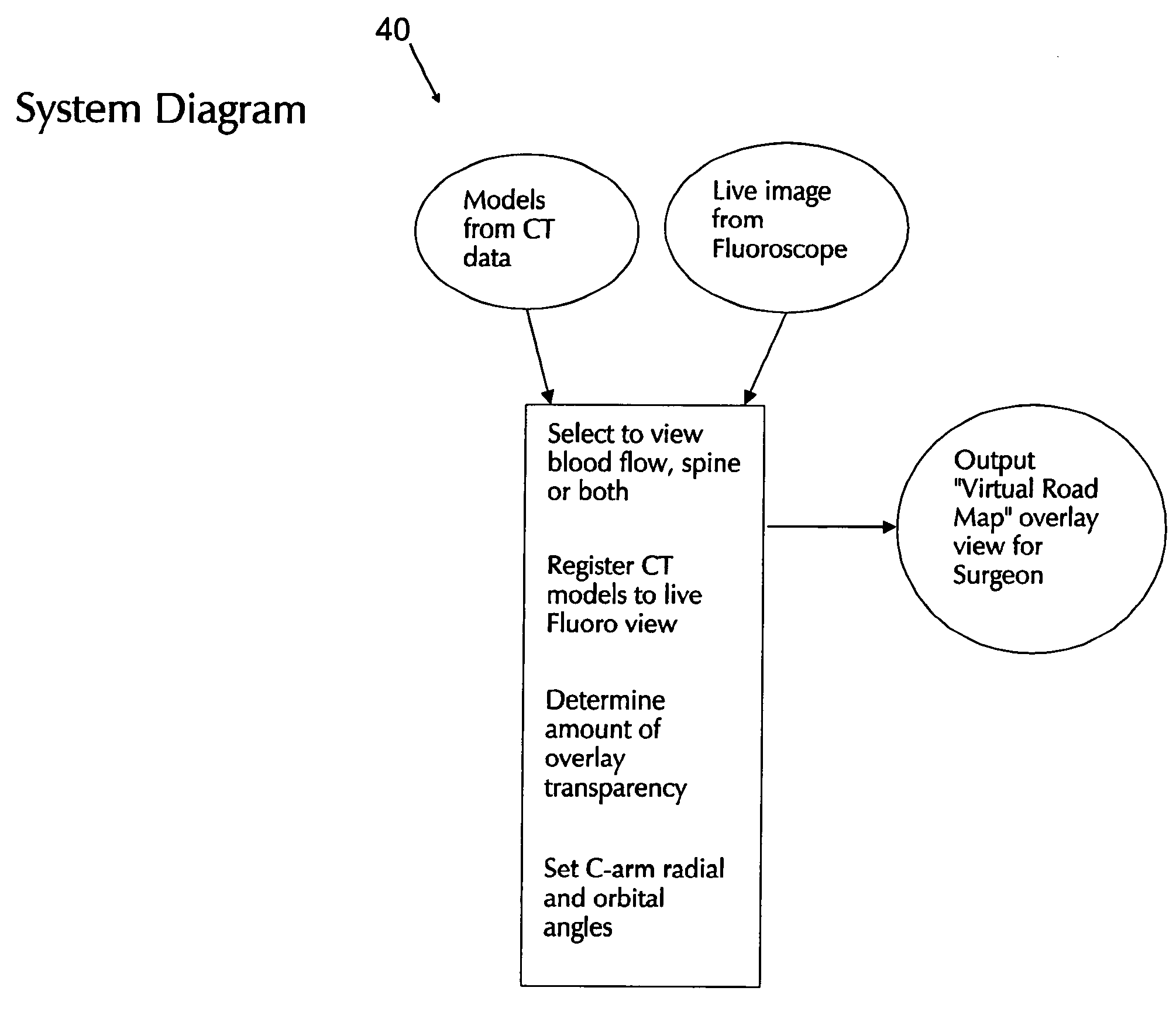
[0037]In order to better understand the concepts of the present invention, it can be helpful to first consider a standard Abdominal Aortic Aneurysm (AAA) patient-specific study as produced by Medical Metrx Solutions of West Lebanon, N.H. (MMS) and utilized in the MMS Preview™ System.

[0038]With the MMS Preview™ System, a virtual, patient-specific 3D model (i.e., the patient-specific AAA study) is constructed from scan data (e.g., CT, CT-angiography, MRA, etc.) to represent the patient's anatomy. More specifically, the virtual 3D model comprises a plurality of virtual objects which are placed in proper registration with one another and which represent specific anatomical objects (e.g., bones, blood vessels, blood flow, etc.). These virtual objects can be grouped together (as appropriate) into virtual, 3D structures, whereby to represent specific anatomical structures or systems (e.g., vascular systems, bone structures, etc.). By way of example, one set of virtual objects is grouped to...


PUM


Abstract

Apparatus and method for producing a virtual road map of a patient's vascular anatomy comprising a virtual 3D model of the patient's vascular and bony structure in proper registration with one another, a fluoroscope for providing real-time images of the bony structure of the patient, registration apparatus for placing the virtual 3D model in proper registration with the patient space of the fluoroscope, bone mask subtraction apparatus for generating a bone mask of the bony structure, and subtracting the same from the real-time images, whereby to create modified fluoroscope images omitting bony structure, and image generating apparatus for generating the virtual road map comprising a composite image combining (i) images of the virtual 3D structure representing the vascular structure, and (ii) modified fluoroscope images omitting bony structure, wherein the images of the virtual 3D structure representing vascular structure are in proper registration with the modified fluoroscope images omitting bony structure.

Description

REFERENCE TO PENDING PRIOR PATENT APPLICATION[0001]This patent application claims benefit of pending prior U.S. Provisional Patent Application Ser. No. 60 / 634,010, filed Dec. 7, 04 by David Chen et al. for INTRAOPERATIVE C-ARM FLUOROSCOPE DATA FUSION SYSTEM, which patent application is hereby incorporated herein by reference.FIELD OF THE INVENTION[0002]This invention relates to medical systems in general, and more particularly to medical systems for visualizing anatomical structures.BACKGROUND OF THE INVENTION[0003]In current medical practice, in order to obtain real-time visualization of the vascular system of a patient, a fluoroscope may be used. The fluoroscope is an X-ray machine which can image moving (or non-moving) internal anatomy. The most common type of fluoroscope found in a vascular surgical suite is the “C-arm” fluoroscope. In the C-arm fluoroscope, the X-ray source and the X-Ray detector are connected together by a “C”-shaped gantry that can rotate (with two degrees of...

Claims


Application Information

Patent Timeline
Patent Type & Authority Patents(United States)
IPC IPC(8): A61B6/00
CPCA61B6/12A61B6/466A61B6/504A61B6/5235A61B19/52A61B6/481A61B6/4405A61B6/4441A61B2019/5289A61B2019/5238A61B90/36A61B2090/364A61B2090/376
Inventor CHEN, DAVIDSAHIN, TUBA
Owner ASTUTE IMAGING LLC
Why Eureka
Try Eureka