Motor retractor and drive control thereof

a technology of motor retractor and drive control, which is applied in the direction of pedestrian/occupant safety arrangement, vehicular safety arrangement, safety belt, etc., can solve the problems of affecting the safety of passengers wearing the webbing, and the current value of the detectable stall current is inevitably large, and achieves excellent

Active Publication Date: 2010-06-01
KK TOKAI RIKA DENKI SEISAKUSHO
View PDF22 Cites 7 Cited by
  • Summary
  • Abstract
  • Description
  • Claims
  • Application Information

AI Technical Summary

Benefits of technology

[0016]Here, in the motor retractor of the above aspect, the controller supplies current of a predetermined current value I0 to the motor when the worn state of the webbing has been lifted and reduces the size of the supply current to a current value I1 that is smaller than the current value I0 at a point in time when a preset amount of the webbing has been taken up or at a point in time when a predetermined amount of time has elapsed after the wearing of the webbing has been lifted.
[0033]As described above, the motor retractor pertaining to the present invention can ensure an appropriate storing speed of a webbing and can stop a motor in a low torque state in abnormal times.

Problems solved by technology

Here, when the biasing force of the biasing member is small, the webbing is not able to be completely taken up and becomes slack, which causes the worsened appearance of the webbing when the webbing is not in use.
On the other hand, when the biasing force of the biasing member is large, this imparts a feeling of tightness to the passenger wearing the webbing.
However, because the current value of the current supplied to the motor is set to be somewhat large on the basis of an appropriate storing speed of the webbing, the current value of the detectable stall current also ends up becoming inevitably large.

Method used


Image

  • Motor retractor and drive control thereof
  • Motor retractor and drive control thereof
  • Motor retractor and drive control thereof

Examples


Embodiment Construction

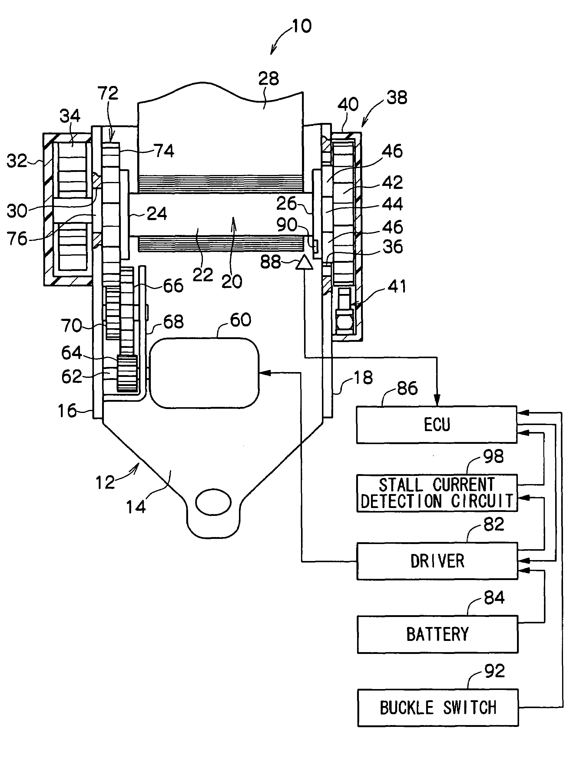
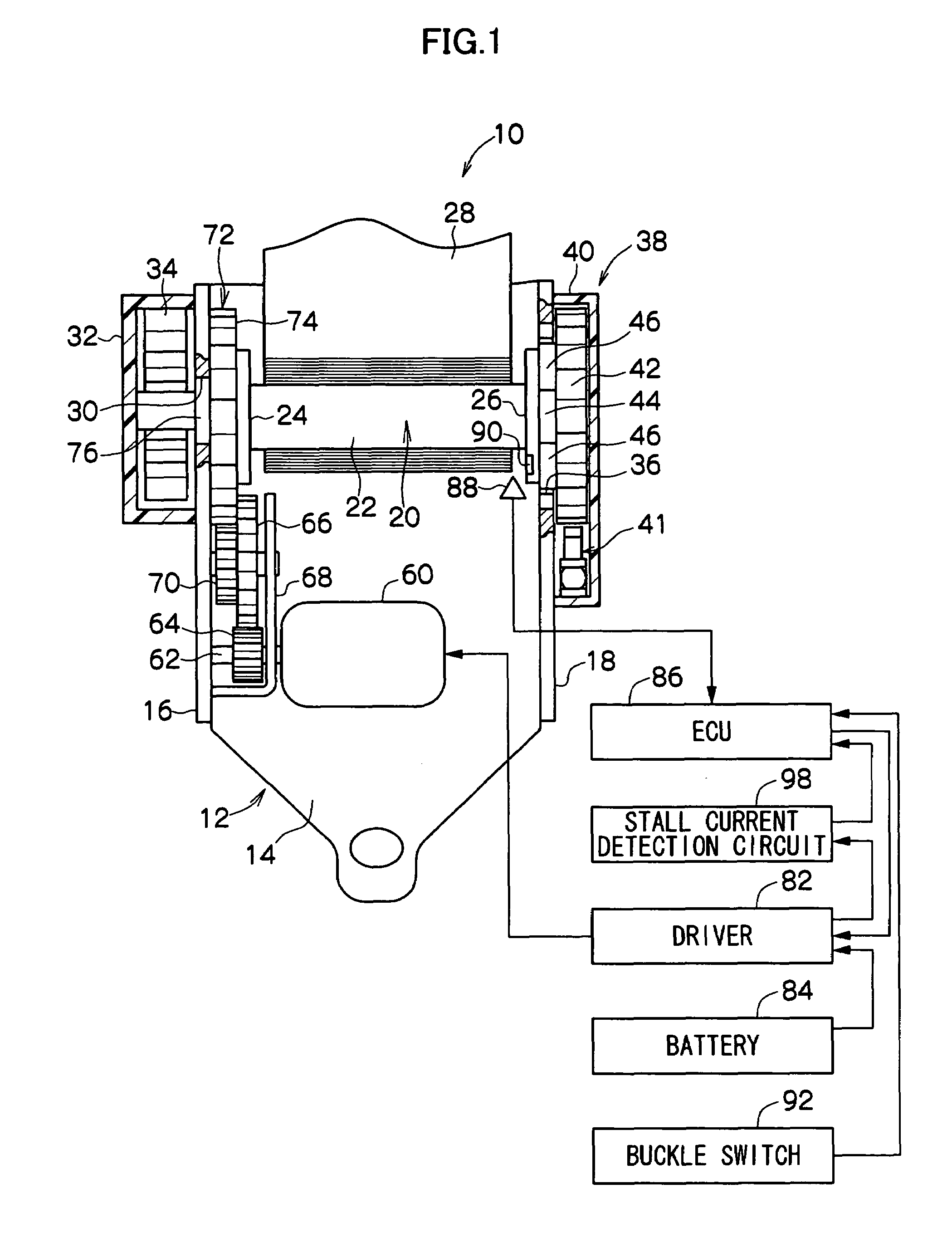
[0038]FIG. 1 is a front sectional view showing the overall configuration of a motor retractor 10 pertaining to an embodiment of the invention.

[0039]As shown in FIG. 1, the motor retractor 10 is disposed with a frame 12. The frame 12 is disposed with a substantially plate-like back plate 14. The back plate 14 is fixed to a vehicle body by unillustrated fastening means such as a bolt, whereby the motor retractor 10 is attached to the vehicle body. Two leg plates 16 and 18 extend parallel to each other from both width-direction ends of the back plate 14. A spool 20 serving as a take-up manufactured by die casting or the like is rotatably disposed between these leg plates 16 and 18.

[0040]The spool 20 is configured by a substantially cylindrical spool body 22 and a pair of flange portions 24 and 26 that are formed in substantially discoid shapes on both end portions of the spool body 20, so that overall the spool 20 has a drum-like shape.

[0041]The base end portion of a webbing 28 formed ...


PUM


Abstract

When the worn state of the webbing is lifted, current of a current value I0 corresponding to the appropriate storing speed of the webbing is supplied to the motor, whereby a take-up shaft rotates and the webbing is taken up. At a point in time when the webbing has been taken up to the extent that the webbing does not hinder the exiting of a vehicle by a passenger, the size of the supply current to the motor is reduced from the initial current value I1 to a current value I1. A reference current value IL of a stall current for determining whether to stop the motor when a foreign object or the like has become entangled between the webbing and an in-vehicle part can also be set to be small in correspondence to the reduced current value I1.

Description

CROSS-REFERENCE TO RELATED APPLICATION[0001]This application claims priority under 35 USC 119 from Japanese Patent Application No. 2005-240053, the disclosure of which is incorporated by reference herein.BACKGROUND OF THE INVENTION[0002]1. Field of the Invention[0003]The present invention relates to a webbing take-up device, and in particular to a motor retractor that can take up a webbing by a motor causing a take-up shaft to rotate.[0004]2. Description of the Related Art[0005]Seat belt devices that restrain passengers seated in seats with a long band-like webbing are attached to vehicles such as passenger cars, and a retractor (webbing take-up device) that stores the webbing in a state where the webbing is taken up such that it can be pulled out is disposed in so-called 3-point seat belt devices.[0006]The retractor is disposed with a take-up shaft, to which the longitudinal-direction base end side of the webbing is fastened and which takes up the webbing from its base end side by ...

Claims


Application Information

Patent Timeline
Patent Type & Authority Patents(United States)
IPC IPC(8): B60R22/34B60R22/48
CPCB60R22/02B60R2022/4666B60R2022/4825B60R2022/4816B60R2022/468
Inventor KOIDE, TERUHIKO
Owner KK TOKAI RIKA DENKI SEISAKUSHO
Why Eureka
Try Eureka