Structure for connecting heat exchangers

a technology of heat exchanger and structure, which is applied in the direction of indirect heat exchangers, machines/engines, light and heating apparatus, etc., can solve the problems of difficult installation of u-bend pipes in small spaces, difficult to form u-bend pipes and weld them to each body part, and high cost of parts and labor. , to achieve the effect of reducing the space for installation, reducing labor, and reducing the cos

Inactive Publication Date: 2010-06-01
T RAD CO LTD
View PDF1 Cites 0 Cited by
  • Summary
  • Abstract
  • Description
  • Claims
  • Application Information

AI Technical Summary

Benefits of technology

[0012]According to the present invention, it is possible to make the labor easy, to reduce the cost, and to reduce the space for installation, because the connecting member can be formed using a press-formable connecting member.
[0013]Furthermore, it is possible to design the shape of the connecting member and the connecting hole freely to some extent because the connecting member is connected to the external face of the each body part around the connecting hole without being connected to the connecting hole directly. Accordingly, it is possible to carry out optimum design by taking into account the flow and resistance of the cooling water and to improve the heat exchange efficiency and reduce the power for transferring the fluid.

Problems solved by technology

However, in the above-mentioned prior structure for connecting heat exchangers, there are problems that it is difficult to form the U-bend pipe and to weld it to the each body part.
Also, costs for parts and labor are expensive, because it is necessary to use the U-bend pipes, which bend radius is small, to connect the heat exchangers.
Furthermore, there is a problem that it is difficult to install the U-bend pipe in the small space, such as the engine room of the vehicle, because a little space is provided to install the U-bend pipe.
In addition, there is a problem that it is difficult to improve the efficiency because fluid resistance and power for transferring the fluid become larger.

Method used


Image

  • Structure for connecting heat exchangers
  • Structure for connecting heat exchangers
  • Structure for connecting heat exchangers

Examples


Embodiment Construction

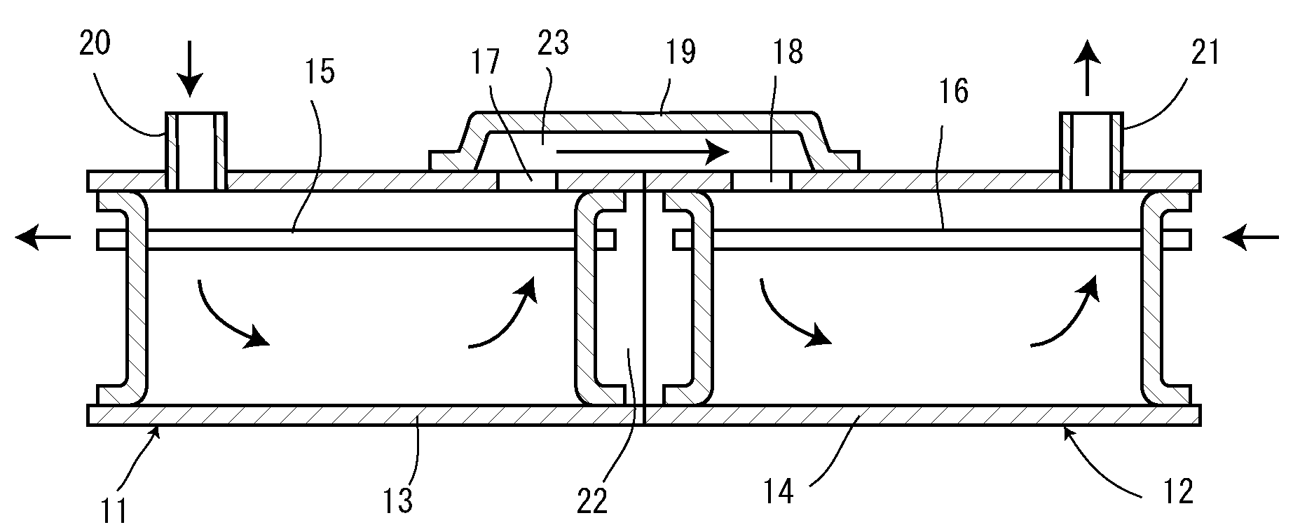
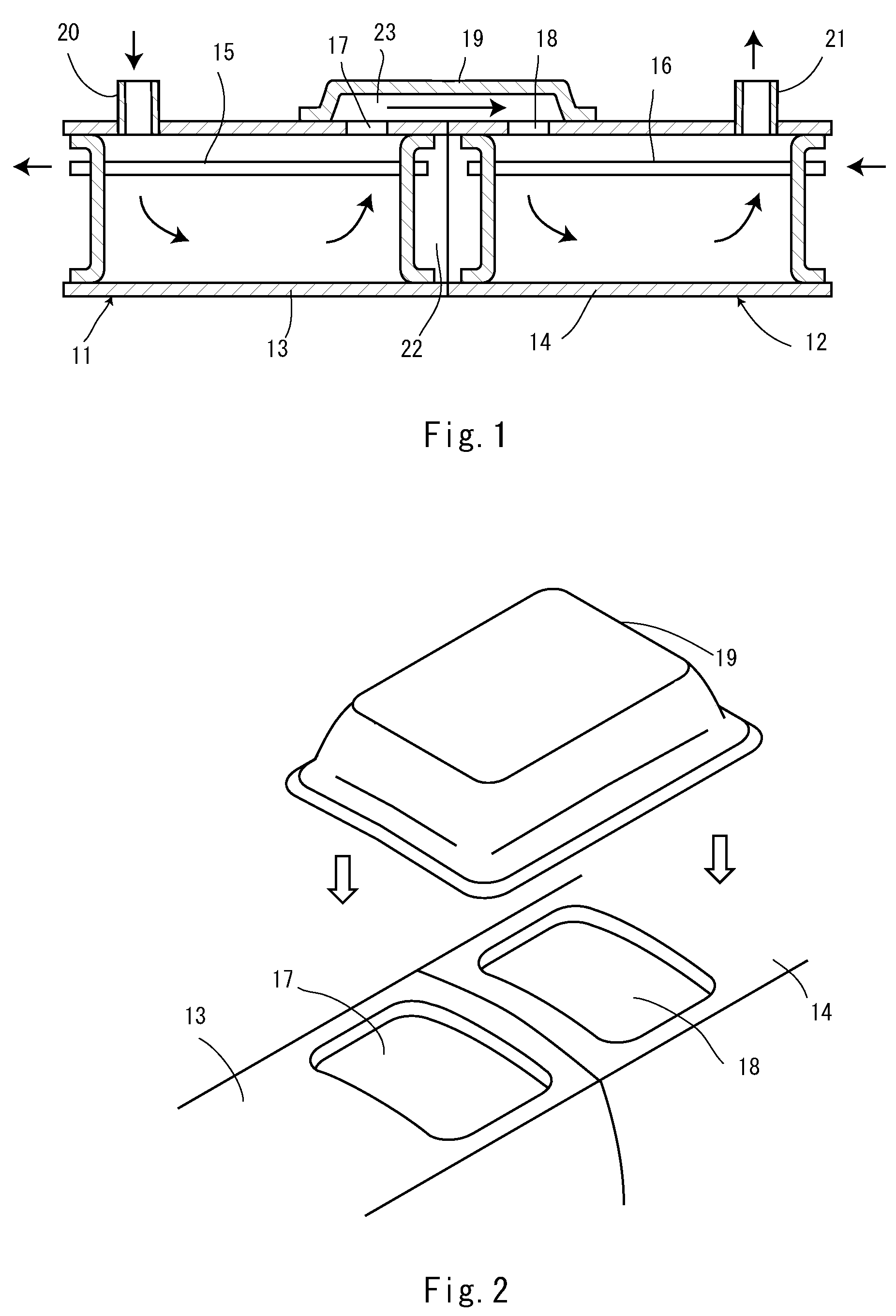
[0018]We will now describe an embodiment of the present invention with reference to the accompanying drawings. FIG. 1 is a section view showing a structure for connecting heat exchangers according to an embodiment of the present invention, and FIG. 2 is a perspective view showing the structure for connecting heat exchangers according to the embodiment of the present invention. We will describe the case to apply the present invention to the EGR cooler as an example thereinafter.

[0019]According to the embodiment of the present invention, the first EGR cooler and the second EGR cooler are configured to be connected to each other in series. Each EGR cooler 11, 12 essentially consists of a body part 13, 14 and heat transfer pipes 15, 16 installed in each body part 13, 14, respectively, so that heat can exchange between cooling water passing through inside of body parts 13, 14 and exhaust gases passing through inside of heat transfer pipes 15, 16. A connecting hole 17, 18 is opened respec...


PUM


Abstract

A connection structure is provided for connecting heat exchangers (11, 12) to each other for exchanging heat between a first fluid flowing in body parts (13, 14) and a second fluid flowing in heat transfer pipes (15, 16) disposed in the body parts (13, 14). The connection structure includes connection holes (17, 18) provided in the body parts (13, 14) of the heat exchangers (11, 12) and a press-formable connection member (19), connected to the outer surfaces of the body parts (13, 14) for fluidly coupling the connecting holes (17, 18) so that the body parts (13, 14) are allowed to communicate with each other.

Description

CROSS-REFERENCE TO RELATED APPLICATION[0001]This application is a national phase for the United States of the PCT Application Serial No. PCT / JP2004 / 017250, filed Nov. 19, 2004, entitled, CONNECTION STRUCTURE OF HEAT EXCHANGER, which is related to and claims priority to Japanese Patent Application No. 2004-135225, filed Apr. 30, 2004, entitled STRUCTURE FOR CONNECTING HEAT EXCHANGERS, the entirety of all of which are incorporated herein by reference.FIELD OF THE INVENTION[0002]The present invention relates to a structure for connecting heat exchangers to exchange heat between cooling fluids that pass through an inside portion of body parts and fluid to be cooled that passes through heat transfer pipes installed in the body parts, such as an EGR (Exhaust Gas Recirculation) cooler and the like to be installed in a vehicle with a diesel engine.BACKGROUND OF THE INVENTION[0003]Recently, the case to install the EGR (Exhaust Gas Recirculation) cooler in vehicles is increasing in order to c...

Claims


Application Information

Patent Timeline
Patent Type & Authority Patents(United States)
IPC IPC(8): F16L55/00F28D7/16F28F9/26
CPCF28D7/16F28F9/26F28D21/0003
Inventor KOBAYASHI, TOSHIMICHI
Owner T RAD CO LTD
Why Eureka
Try Eureka