Binding processing apparatus

a processing apparatus and binding technology, applied in the field of binding processing apparatus, can solve the problems of not present a processing apparatus automatic, difficult to contain a number of coils, and difficult to automate the mounting operation of the binding binder

Active Publication Date: 2010-06-01
MAX CO LTD
View PDF22 Cites 6 Cited by
  • Summary
  • Abstract
  • Description
  • Claims
  • Application Information

AI Technical Summary

Benefits of technology

[0006]Hence, it is an object of the invention to provide a binding processing apparatus capable of continuously executing a series of binding processings from forming a punch hole to fitting a binder.

Problems solved by technology

Although according to the processing method of binding sheets by a coil binder, or a binder of a type of a series of rings, in comparison with the method of binding sheets by a staple or the method of binding sheets by a glue, there is achieved an advantage that an excellent outlook is provided and handling of sheets as a document is also facilitated, automation of a binder mounting operation is not easy, and there is not present a processing apparatus automating a series of binding processings from forming punch holes to fitting a binder.
Although according to the coil binding apparatus of JP-A-2002-337474, an object of automating to fit the coil is achieved, at each time of binding a copy of brochure, a single piece of coil needs to be mounted to the apparatus, which is not applicable to a use requesting an automatic continuous processing function (a use as a post processing apparatus of a copier or the like).
Further, it is not easy to contain a number of coils in a cartridge or the like owing to the shape or constitute a continuous automatic feeding mechanism therefor and it is difficult to constitute a binding processing apparatus operated in cooperation with a copier or the like.

Method used


Image

  • Binding processing apparatus
  • Binding processing apparatus
  • Binding processing apparatus

Examples


first exemplary embodiment

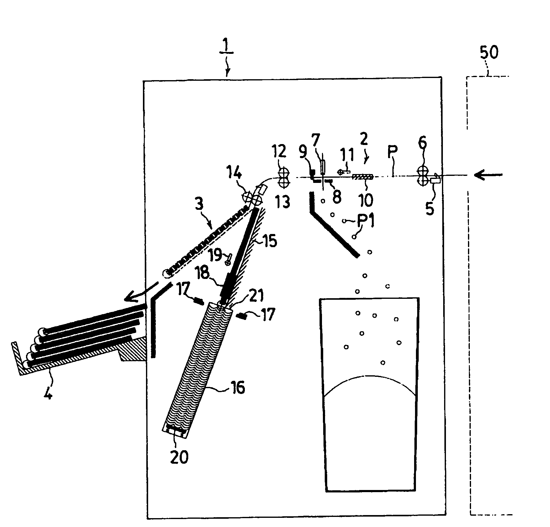
[0023]FIG. 1 shows a constitution of a binding processing apparatus 1 according to a first exemplary embodiment of the invention. Sheets printed by the printing apparatus 50 of a copier, a page printer or the like are successively fed to the binding processing apparatus 1 by a sheet feeding mechanism of the printing apparatus 50 and drawn into the binding processing apparatus 1. The binding processing apparatus 1 is a compound machine (ALL IN ONE MACHINE) integrated with a punch mechanism 2 and a binding processing mechanism 3. The sheets P fed from the printing apparatus 50 are formed with punch holes by the punch mechanism 2, fed to the binding processing mechanism 3, fitted with a series ring type binder at the punch holes by the binding processing mechanism 3 and discharged to the stack tray 4.

[0024]Details of binding processing apparatus 1 will be explained as follows. A sheet detecting sensor 5 and a pair of upper and lower sheet feeding rollers 6 are arranged at a vicinity of...

second exemplary embodiment

[0035]FIG. 6 shows the binding processing apparatus 41 according to a second exemplary embodiment of the invention. Although the binding processing apparatus 41 is constructed by a constitution basically the same as that of the binding processing apparatus 1 of the first exemplary embodiment, whereas the punch holes are formed on the front side in the direction of feeding the sheet according to the first exemplary embodiment, according to the binding processing apparatus 41 of the second exemplary embodiment, the punch holes are formed on the rear side in the direction of feeding the sheet. The series punch mechanism comprising the punch block 7 and the die 8 and the stopper plate 9 are arranged to be proximate to the introducing port of sheets. When the sheet is fed by the sheet feeding roller 6, the stopper plate 9 is moved up and does not hinder the sheet P from passing and the stopper plate 9 is moved down after the sheet P has completely been fed. Thereafter, the sheet feeding ...


PUM


Abstract

A binding processing apparatus 1 is provided with a punch mechanism 2 and a binding processing mechanism 3 for executing a binding processing by a binder. When a sheet P is fed from a printing apparatus 50 of a copier or the like, the sheet is butted to a stopper plate 9 of the punch mechanism, sheet aligning sliders 10 push both left and right sides thereof to position and punch holes are formed by a punch block 7 and a die 8. Thereafter, the sheet is fed to a sheet tray 15 of the binding processing mechanism, one set of the sheets are aligned and a ring shape binder is pinched by a pusher 17 to fit the ring shape binder to the punch holes of the sheets, and a brochure subjected to a binding processing is discharged to a stack tray 4. A binder cartridge 16 can contain a number of the binders and the binding processing can be executed continuously.

Description

TECHNICAL FIELD[0001]The present invention relates to a binding processing apparatus for carrying out a series of processings until a sheet is formed with a punch hole and fitted with a ring type binder to bind.BACKGROUND ART[0002]There has been diffused a copier incorporating an electric stapler and a post processing function of subjecting each set of sheets successively fed from a copy mechanism to book binding by binding a set by a staple. Further, as a book binding by binding means other than a staple, there is also known book binding means of a coil binder, a comb binder comprising a series of rings in a comb-like shape or the like as means having a further excellent outlook and facilitating to handle and leaf pages. As the apparatus with an object of a binding processing connected to a copier as a post processing apparatus for binding sheets by the binding means, there is known a processing apparatus of successively receiving sheets which are copied or printed with images, for...

Claims


Application Information

Patent Timeline
Patent Type & Authority Patents(United States)
IPC IPC(8): B42B5/08B42C99/00B42F13/22
CPCB42B5/08B42B5/00
Inventor KURABAYASHI, ATSUSHIYOSHIE, TORUHASEGAWA, TAKAO
Owner MAX CO LTD
Why Eureka
Try Eureka