Continuously variable transmission

a transmission and continuous technology, applied in the direction of friction gearings, gearing elements, engine controllers, etc., can solve the problems of inability to meet the intended use of the intended use of the intended use of the intended use of the intended use, the proposed continuously variable transmission (cvt) is typically too heavy and inefficient, and the proposed device for reducing the dead spot is relatively inefficient and typically falls into disuse. , to achieve the effect of low cost and relatively compact transmission

Inactive Publication Date: 2010-06-01
MAHEU PIERRE
View PDF7 Cites 69 Cited by
  • Summary
  • Abstract
  • Description
  • Claims
  • Application Information

AI Technical Summary

Benefits of technology

[0023]The transmission is relatively compact, light and robust and is manufacturable at a relatively low cost.
[0024]Furthermore, in some embodiments of the invention, the transmission does not require any external power source to vary its transmission ratio. In this case, an embodiment of the invention including only mechanical components, as opposed to electronic components, is particularly advantageous.

Problems solved by technology

In addition, in most motions, power is not uniformly produced over the duration of the stroke.
The few continuously variable transmissions (CVTs) that have been proposed for bicycles are typically too heavy and too inefficient to be suitable to their intended use.
Unfortunately, most of the proposed devices for reducing dead spots are relatively inefficient and typically fall into disuse after only a few years on the market.
Accordingly, there is no means for adapting rotation speeds of the handrim or wheel to the requirements of the human in wheelchairs.
However, similar problems are encountered in many other human power applications and in motor-driven applications.

Method used


Image

  • Continuously variable transmission
  • Continuously variable transmission
  • Continuously variable transmission

Examples


Embodiment Construction

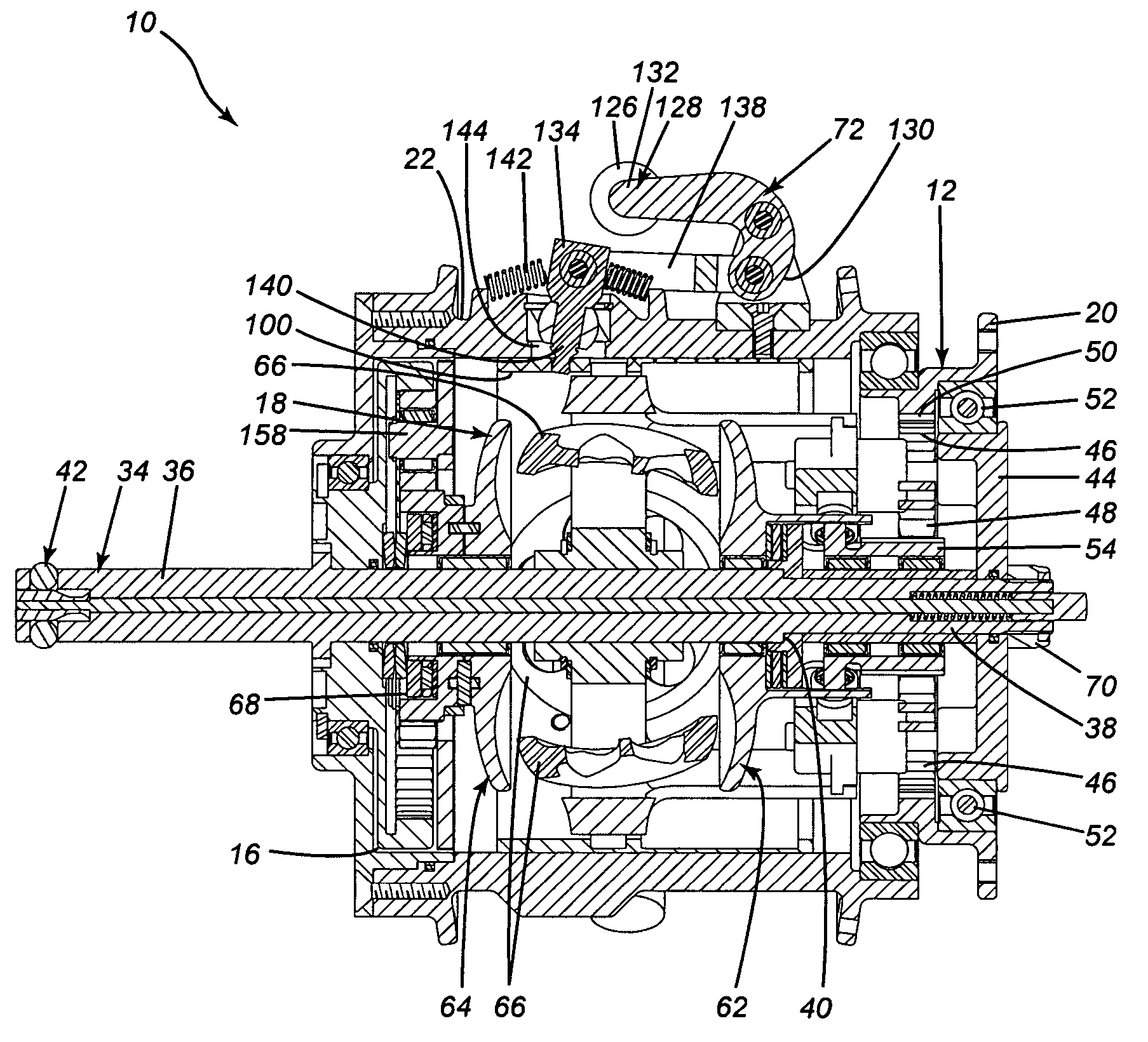
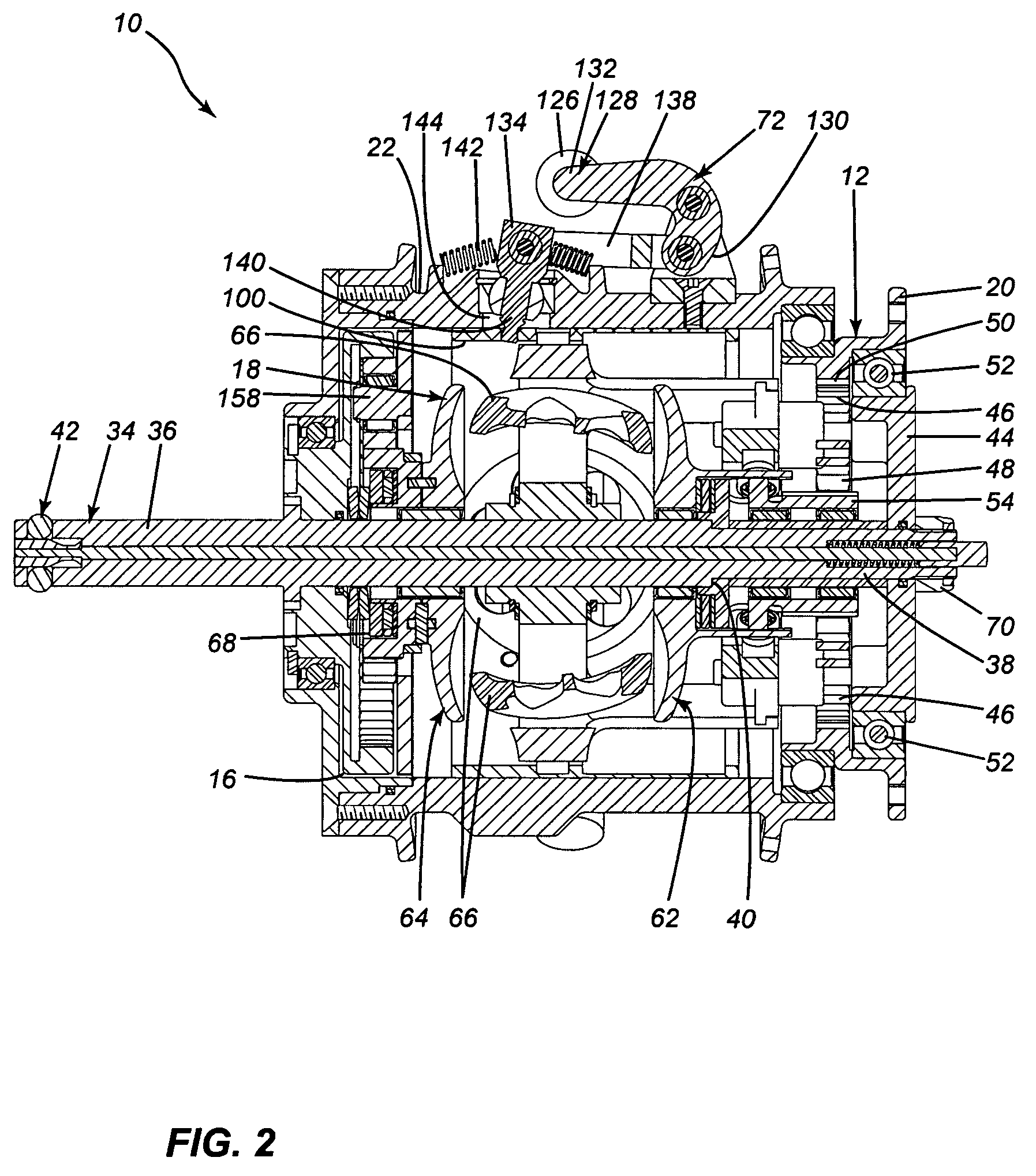
[0042]FIG. 4 illustrates a variable ratio transmission 10 for receiving an input rotational motion having an input speed and a corresponding input torque, and for providing an output rotational motion having an output speed and a corresponding output torque. The variable ratio transmission 10 includes an input stage 12 receiving the input rotational motion. The variable ratio transmission 10 also includes an intermediate stage 14 including a variable ratio transmission assembly 18, the intermediate stage 14 being mechanically coupled to the input stage 12. The variable ratio transmission 10 further includes an output stage 16 mechanically coupled to the intermediate stage 14. The output stage 16 provides the output rotational motion.

[0043]The variable ratio transmission 10 mechanically couples an input member 20 of the input stage 14 to an output member 22 of the output stage 16 and allows the conversion of an input rotational motion of the input member 20 into an output rotational ...


PUM


Abstract

A variable ratio transmission for mechanically coupling an input member to an output member, the variable ratio transmission allowing the conversion of an input rotational motion of the input member into an output rotational motion of the output member, the input rotational motion having an input speed and an input torque and the output rotational motion having an output speed and an output torque. The variable ratio transmission includes a variable ratio transmission assembly mechanically coupled to the input member and to the output member for rotating the output member at the output speed in response to the input member being rotated at the input speed, the variable ratio transmission assembly defining a transmission ratio between the output speed and the input speed, the transmission ratio being variable; and a ratio controller mechanically coupled to the variable ratio transmission assembly and to the input member for automatically adjusting the transmission ratio as a function of the input torque.

Description

[0001]This application claims priority from U.S. Provisional Patent Application Ser. No. 60 / 614,464 filed Oct. 1, 2004.FIELD OF THE INVENTION[0002]The present invention relates to transmissions. More specifically, the present invention is concerned with a continuously variable transmission.BACKGROUND OF THE INVENTION[0003]Transmissions allow the variation of a ratio of rotation speeds between an input and output. As such, they allow controlling the rotation speed at their output when the input speed is either larger or smaller than the output speed.[0004]In many applications, the input speed is determined by a power band of a power source connected to the input of the transmission. Indeed, many power sources provide an optimal torque or power over only a limited range of rotation speeds. For example, this is the case wherein the power source is an animal or a human.[0005]Typically, humans provide power for locomotion or other purposes through a repetitive movement. In this document,...

Claims


Application Information

Patent Timeline
Patent Type & Authority Patents(United States)
IPC IPC(8): F16H15/38
CPCF16H15/38F16H63/067Y10T477/619
Inventor MAHEU, PIERREDAHME, JEAN-FRANCOIS
Owner MAHEU PIERRE
Why Eureka
Try Eureka