Adjustable-viewing-angle liquid crystal display

a liquid crystal display and viewing angle technology, applied in the field of display, can solve the problems of user privacy not being protected by the lcd, backlight module still not being able to provide real parallel backlight, user data security not being maintained, etc., and achieve the effect of maintaining the operating quality of the lcd and enhancing the practicality of the lcd

Active Publication Date: 2010-06-01
AU OPTRONICS CORP
View PDF12 Cites 14 Cited by
  • Summary
  • Abstract
  • Description
  • Claims
  • Application Information

AI Technical Summary

Benefits of technology

[0010]It is therefore an object of the invention to provide an adjustable-viewing-angle LCD. The design of incorporating a viewing-angle-adjusting device allows the user to adjust the viewing-angle of the LCD by switching a wide-viewing-angle mode or a narrow-viewing-angle mode, not only protecting personal privacy and maintaining data security, but also largely enhancing the practicality of the LCD. Besides, when the user switches the LCD's viewing-angle mode, the contrast and brightness of the LCD do not change, so that the user who views the LCD from the front will not sense any change in contrast and brightness and that the operating quality of the LCD can be maintained.

Problems solved by technology

Take the notebook computer for example, when using a notebook computer, the viewing angle design of a conventional LCD cannot protect the privacy of the user, and the frame displayed on the LCD can be easily viewed by a bystander in a squint direction.
However, present luminous technology of backlight module is still unable to provide real parallel backlight.
Although the LCD 10 is already at the narrow-viewing-angle mode shown in FIG. 1A, the user cannot really protect personal privacy and maintain data security.

Method used


Image

  • Adjustable-viewing-angle liquid crystal display
  • Adjustable-viewing-angle liquid crystal display
  • Adjustable-viewing-angle liquid crystal display

Examples


first preferred embodiment

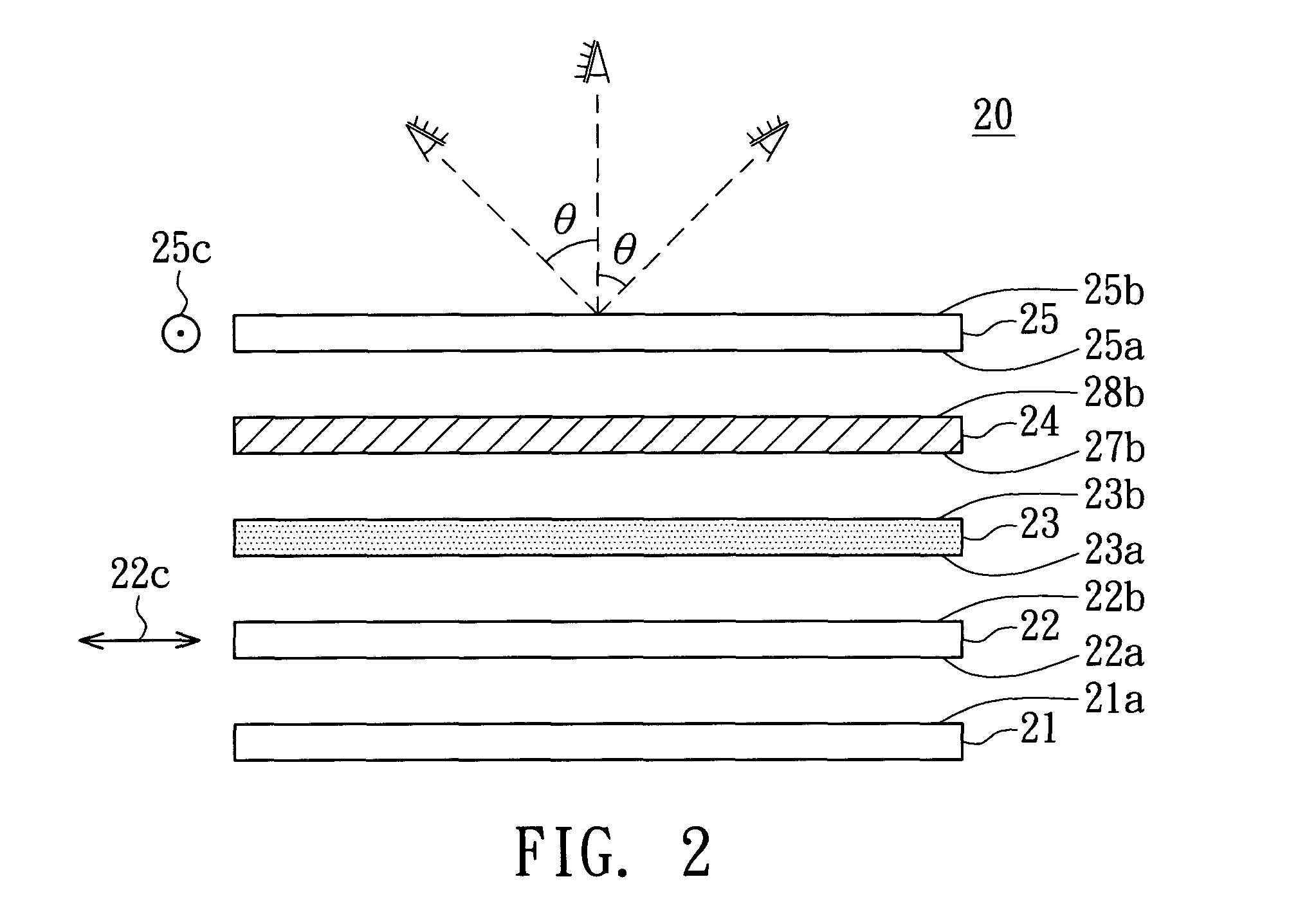
[0073]Referring to FIG. 2, a side view of a LCD with adjustable-viewing-angle according to the first preferred embodiment of the invention is shown. In FIG. 2, LCD 20 comprises a backlight module 21, a first polarizer 22, an LCD panel 23, a viewing-angle-adjusting device 24 and a second polarizer 25. The backlight module 21 has a light-emitting surface 21a while the first polarizer 22 has a first surface 22a and a second surface 22b corresponding to each other. The LCD panel 23 has a third surface 23a and a fourth surface 23b corresponding to each other while the second polarizer 25 has a fifth surface 25a and a sixth surface 25b corresponding to each other. The first polarizer 22 is disposed on the light-emitting surface 21a with the first surface 22a facing the light-emitting surface 21a while the LCD panel 23 is disposed on the second surface 22b with the third surface 23a facing the second surface 22b. The second polarizer 25 is disposed on the fourth surface 23b with the fifth ...

second preferred embodiment

[0089]Referring to FIG. 9, a side view of the LCD with adjustable-viewing-angle according to the second preferred embodiment of the invention is shown. The LCD 40 in the present preferred embodiment differs with the LCD 20 in the first preferred embodiment in that the former further comprises a first compensation film 41a and a second compensation film 41b. As for the remaining identical constituting elements, the same labels are used but the details are not repeated here. In FIG. 9, the first compensation film 41a is disposed between the first polarizer 22 and the LCD panel 23 while the second compensation film 41b is disposed between the second polarizer 25 and the viewing-angle-adjusting device 24. The first compensation film 41a and the second compensation film 41b are for compensating the leak light at the dark state of the first polarizer 22 and the second polarizer 24 and the leak light at the dark state of the liquid crystal when viewed by the viewer views in a squint direct...

third preferred embodiment

[0091]Referring to FIG. 11, a side view of the LCD with adjustable view angle according to the third preferred embodiment of the invention is shown. The LCD 50 in the present preferred embodiment differs with the LCD 20 in the first preferred embodiment in that the LCD panel 23 is positioned between the viewing-angle-adjusting device 24 and the second polarizer 25. The viewing-angle-adjusting device 24 is disposed on the second surface 22b with the second substrate surface 27b facing the second surface 22b of the first polarizer 22. The LCD panel 23 is disposed on the fourth substrate surface 28b with the third surface 23a facing the fourth substrate surface 28b. The first polarizer 25 is disposed on the fourth surface 23b with the fifth surface 25a facing the fourth surface 23b. However, anyone who is familiar with the technology of the invention will understand that the technology of the invention is not limited thereto. For example, the first compensation film can be positioned b...


PUM

PropertyMeasurementUnit
azimuth angleaaaaaaaaaa

Abstract

An LCD includes a backlight module, two polarizers, an LCD panel and a viewing-angle-adjustable device. The polarizers are disposed over the backlight module. The LCD panel and the first viewing-angle-adjusting device are disposed between the polarizers. The viewing-angle-adjusting device comprises a first substrate, a first electrode, a liquid crystal layer, a second electrode and a second substrate. The first electrode is disposed on the first substrate. The liquid crystal layer is disposed on the first electrode. The second electrode and the second substrate are disposed on the liquid crystal layer. The first liquid crystal layer is sealed between the first substrate and the second substrate. The second electrode is disposed on the bottom surface of the second substrate.

Description

[0001]This application claims the benefit of Taiwan application Serial No. 93118355, filed Jun. 24, 2004, the subject matter of which is incorporated herein by reference.BACKGROUND OF THE INVENTION[0002]1. Field of the Invention[0003]The invention relates in general to a display, and more particularly to an adjustable-viewing-angle LCD.[0004]2. Description of the Related Art[0005]With the advantages of low radiation, compactness and slimness, liquid crystal display (LCD) has gained a wide popularity. Due to the features of higher brightness and wider viewing angle, thin film transistor (TFT) LCD is particularly popular among high-level products. A conventional TFT LCD comprises a backlight module, an upper polarizer, an LCD panel and a lower polarizer, wherein the LCD panel is disposed between the upper polarizer and the lower polarizer. When backlight module is disposed beneath the lower polarizer, the light transmission line of the upper polarizer and that of the lower polarizer a...

Claims


Application Information

Patent Timeline
Patent Type & Authority Patents(United States)
IPC IPC(8): G06F3/038G02F1/1337G09G5/00H04N5/238G09F19/14G02F1/133G02F1/1333G02F1/1335G02F1/139
CPCG02F1/1323G02F1/1333G02F1/1393G02F1/133753G02F1/13336
Inventor TSAI, MENG-CHANGCHANG, CHIH-MING
Owner AU OPTRONICS CORP
Why Eureka
Try Eureka