Housings and devices for disk drives

a technology for housing and disk drives, applied in the direction of cathode-ray oscilloscopes, electrical apparatus casings/cabinets/drawers, instruments, etc., can solve the problem of environmental testing taking longer than interface testing, and achieve the effect of more stable and predictable operating characteristics

Active Publication Date: 2010-06-01
XYRATEX TECH LTD
View PDF34 Cites 70 Cited by
  • Summary
  • Abstract
  • Description
  • Claims
  • Application Information

AI Technical Summary

Benefits of technology

[0034]The preferred embodiment of the device is able to damp vibrations arising from outside the device affecting a disk drive received in the device, and to damp vibrations arising through operation of the disk drive. In practice, the disk drive is rigidly connected to the device whereas the device is “soft” mounted within apparatus such as a frame that supports many such devices.
[0035]The damping material is preferably arranged to be at an angle to the rotational axis of a disk drive received in use in the device so that the damping material damps vibrations by a combination of shear and compression / extension of the damping material. Thus, the damping material preferably operates not exclusively in shear mode or compression / extension mode, which makes the material more durable and its operating characteristics more stable and predictable over a wider range of operating conditions.

Problems solved by technology

In practice, environment testing takes longer than interface testing.

Method used


Image

  • Housings and devices for disk drives
  • Housings and devices for disk drives
  • Housings and devices for disk drives

Examples


Embodiment Construction

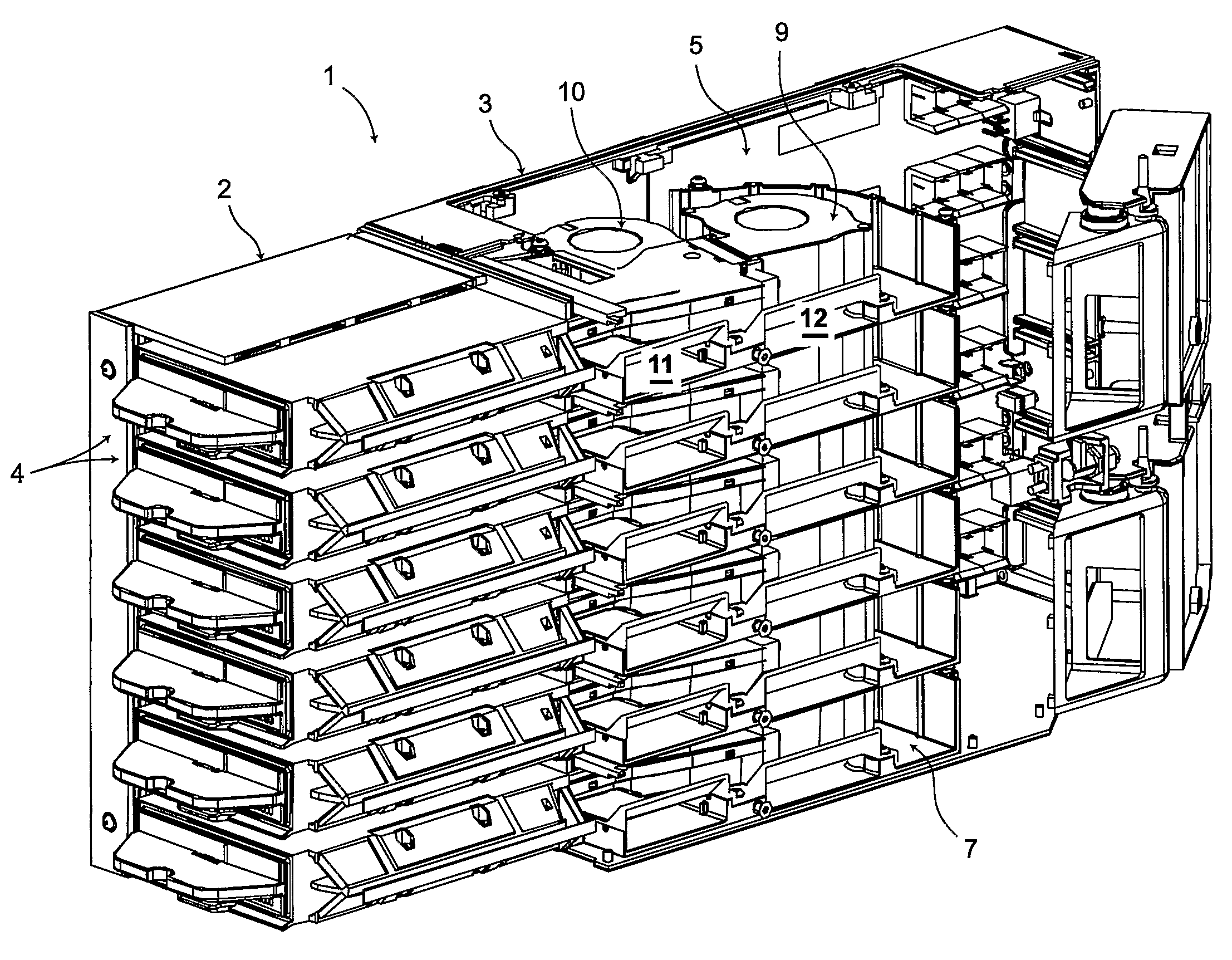
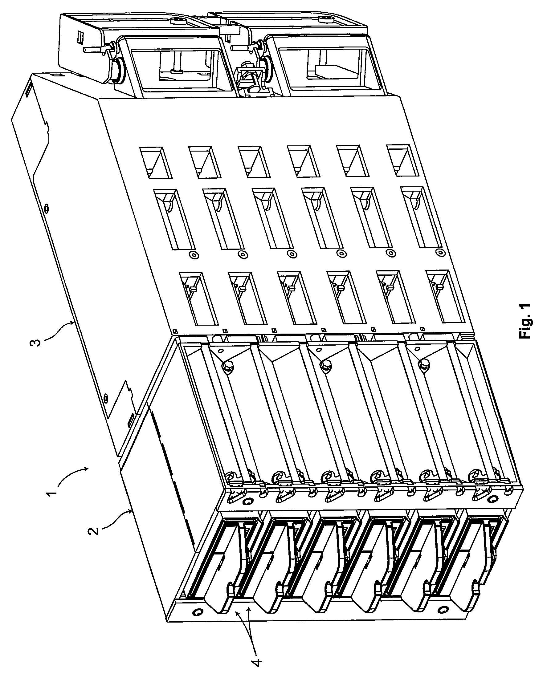
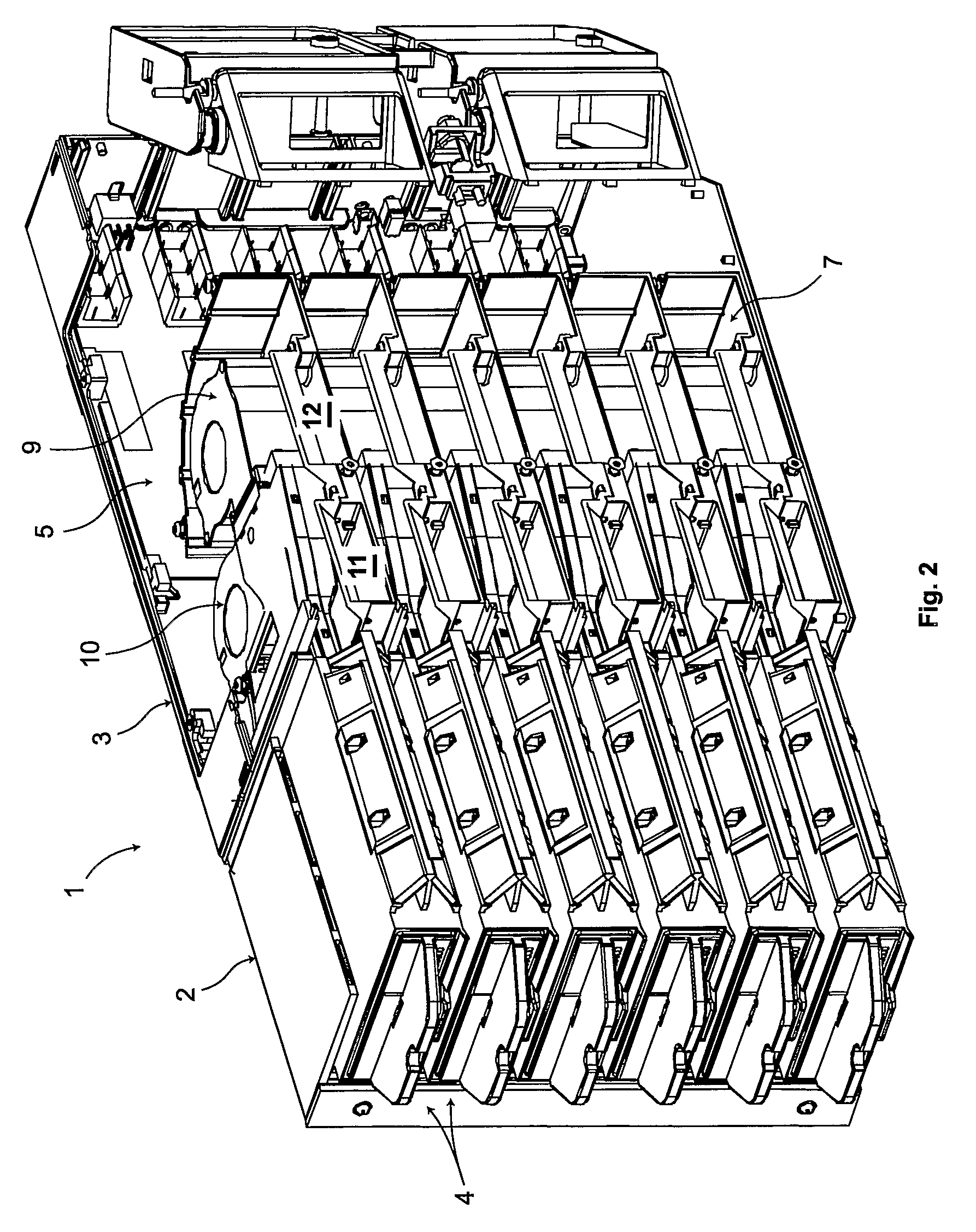
[0050]Referring first to FIGS. 1 and 2, a disk drive test apparatus 1 has a front section 2 and a rear section 3. In this example, the front section 2 is removably fixed to the rear section 3. It will be understood that the terms “front” and “rear” are used by convention, the front section 2 being where the disk drives are located in use and the rear section 3 containing the electronics, etc., as will be discussed further below.

[0051]In the example shown, the apparatus 1 can house a maximum of six disk drives in separate bays 4 which are arranged vertically one above the other. In use, the apparatus 1 is fixed to a large, typically steel, frame (not shown) with very many other such apparatus 1 so that hundreds or even thousands of disk drives can be carried within the frame at a time. In a preferred embodiment, robots are used to insert disk drives into and remove disk drives from the apparatus 1.

[0052]Referring particularly now to FIGS. 2 and 3, the rear section 3 has a vertically ...


PUM


Abstract

A disk drive test apparatus has a plurality of bays each for receiving a respective disk drive to be tested. A plurality of card slots are provided each for receiving a test card via which a disk drive can be tested. Each of the test cards is either an environment test card or an interface test card. The card slots and the test cards are arranged such that each card slot (6) can selectively receive an environment test card or an interface test card. Other arrangements for disk drive test apparatus or disk drive mounting apparatus are disclosed.

Description

CROSS REFERENCE TO RELATED APPLICATIONS[0001]This is the U.S. National Phase of PCT / GB2005 / 003490, filed Sep. 9, 2005, which in turn claims priority to U.S. provisional application Ser. No. 60 / 610,532, filed Sep. 17, 2004, both of which are incorporated herein in their entirety by reference.BACKGROUND OF THE INVENTION[0002]1. Field of the Invention[0003]The present invention relates generally to housings and devices for disk drives.[0004]2. Discussion of Related Art[0005]During manufacture of disk drive units, it is necessary to test the disk drive units to ensure that they meet the required specification. For example, the magnetic recording surfaces of the disks are tested for defects and the electronics of the disk drive are also tested. As part of the testing operation, the temperature of the disk drive unit is varied across a wide range to ensure that the performance of the disk drive over that temperature range is satisfactory.[0006]For this purpose, the disk drive units are mo...

Claims


Application Information

Patent Timeline
Patent Type & Authority Patents(United States)
IPC IPC(8): G01R33/12G01M99/00
CPCG06F1/184G06F1/187G06F1/20G11B33/144G11B33/022G11B33/08G11B33/128G06F1/206G01R13/28G06F11/267G11B33/12G11B33/14G01R31/28
Inventor ATKINS, ANDREW WILLIAMBAILEY, STEVE ANDREWFARQUHAR, DAVID RONALD BAINORRISS, DAVID JOHNRICHARDSON, KEVIN
Owner XYRATEX TECH LTD
Why Eureka
Try Eureka