Carriage for image scanning unit including radiation plate for conducting heat

a radiation plate and heat conductor technology, applied in the direction of instruments, electrographic process devices, optics, etc., can solve the problems of affecting image scanning, deteriorating luminous efficiency, and relatively long light emitting period, and achieve the effect of suppressing the accumulation of heat at the light sour

Inactive Publication Date: 2010-06-01
BROTHER KOGYO KK
View PDF34 Cites 0 Cited by
  • Summary
  • Abstract
  • Description
  • Claims
  • Application Information

AI Technical Summary

Benefits of technology

[0007]The present invention is advantageous in that there is provided an improved carriage, image scanning unit, and multifunction peripheral having an image scanning function, which are configured such that accumulation of heat at the light source is suppressed.

Problems solved by technology

In particular, when a plurality of original documents are scanned continuously, or a relatively long time is spent for scanning an image at a high resolution, light emitting period becomes relatively long.
There are light sources (e.g., a cold cathode tube) which have characteristics such that luminous efficiency is deteriorated as the temperature increase.
When the luminous efficiency is deteriorated, the light intensity becomes insufficient, which may adversely effect image scanning.

Method used


Image

  • Carriage for image scanning unit including radiation plate for conducting heat
  • Carriage for image scanning unit including radiation plate for conducting heat
  • Carriage for image scanning unit including radiation plate for conducting heat

Examples


first embodiment

General Configuration of a Multifunction Peripheral

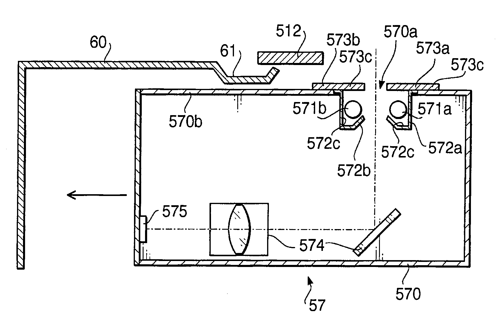
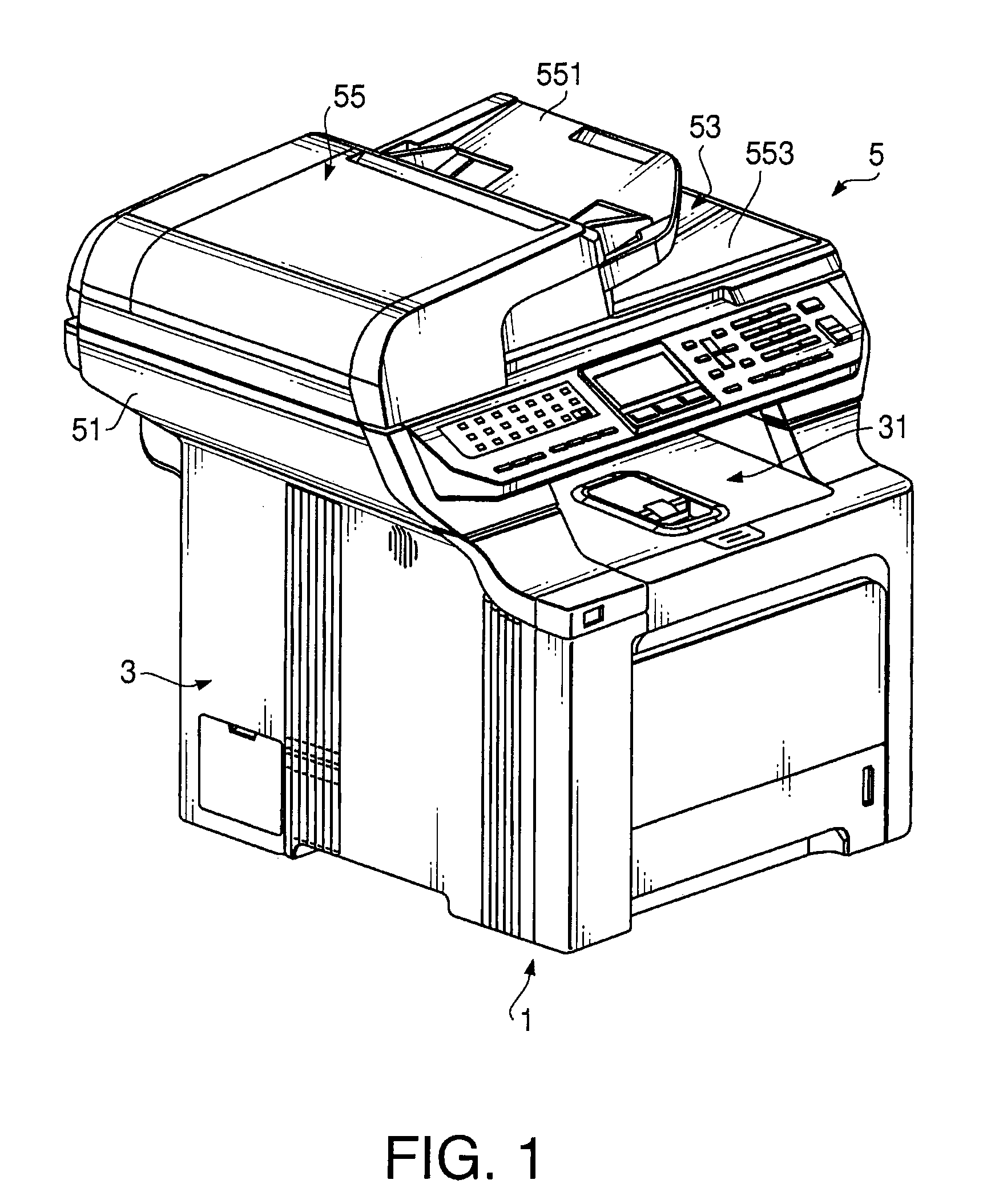
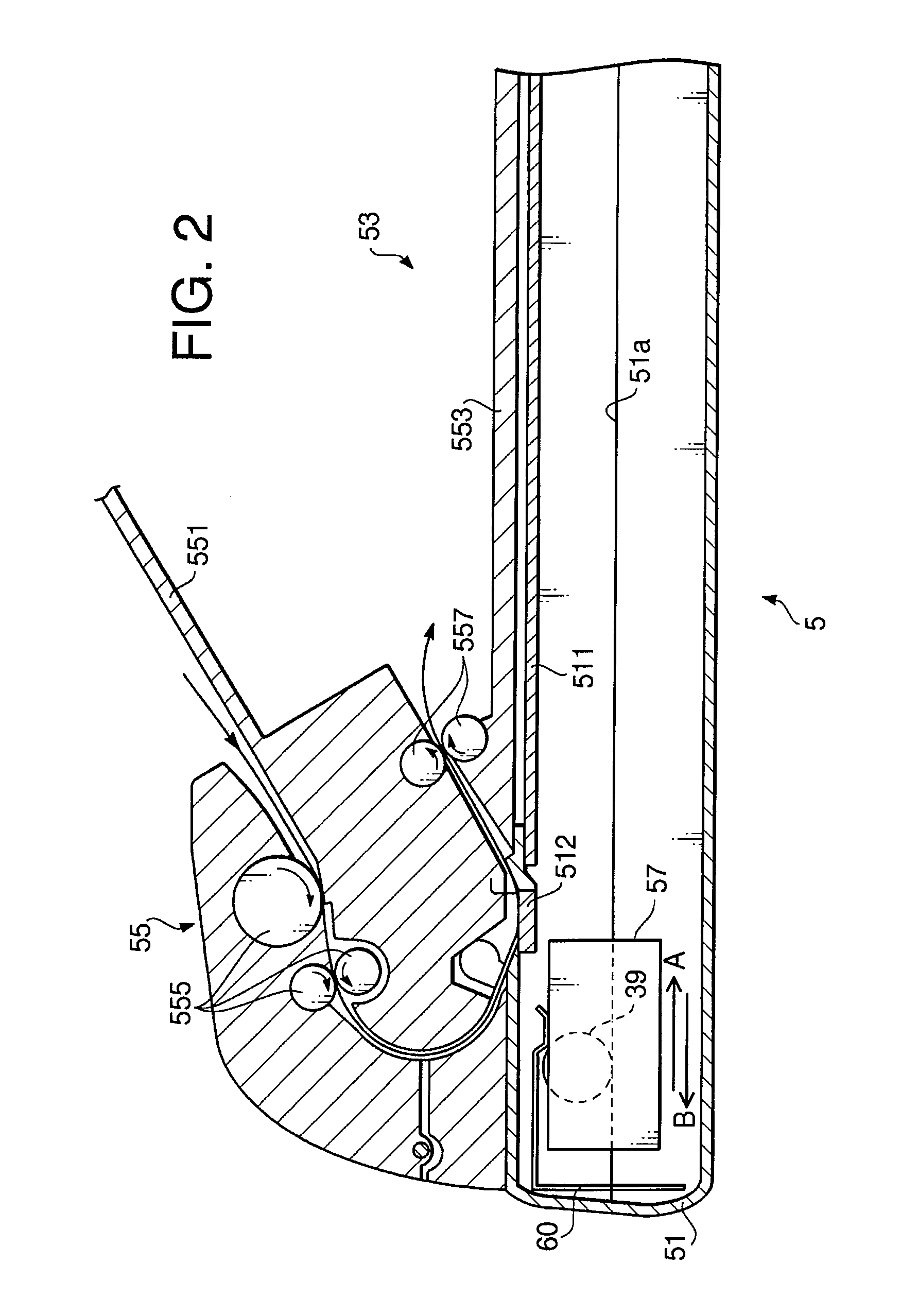
[0023]FIG. 1 is a perspective view of a multifunction peripheral 1 (hereinafter referred to as the “MFP”) according to the present invention. As shown FIG. 1, the MFP is provided with an image forming unit 3 and an image scanning unit 5. The image scanning unit 5 is above the image forming unit 3 and a sheet discharging space 31 is defined between the image forming unit 3 and the image scanning unit 5.

[0024]The image forming unit 3 is an electrophotographic type image forming unit which prints an image scanned by the image scanning unit 5 on a recording sheet and discharges the sheet to the sheet discharging space 31. It should be noted that the image forming device 3 may not be the electrophotographic type but an inkjet type or a thermal type image forming unit.

[0025]The image scanning unit 5 is includes a CCD (Charge Coupled Device) as an image sensor, a main body 51 and a document holder 53. The document holder 53 is supported by...

second embodiment

[0047]According to the first embodiment, two radiation plates 573a and 573b are separately arranged in the carriage 57 in the first embodiment. It should be noted that the radiation plates may be connected or formed as a single member. According to a second embodiment described hereinafter, the radiation plates are configured so that the two radiation plates can conduct heat to each other. According to the description of the second embodiment, a carriage 67 has substantially the same configuration as the carriage 57 according to the first embodiment. Therefore, only the different members such as radiation plates 673a and 673b, etc. are assigned reference numbers different from those of the first embodiment, while the same reference numbers are assigned to the members which are the same as those of the first embodiment and description thereof will be omitted for brevity.

[0048]FIG. 5 is a perspective view of the carriage 67 according to the second embodiment.

[0049]As shown in FIG. 5, ...

third embodiment

[0052]According to the second embodiment, the connecting sections 674 connecting the radiation plates 673a and 673b are arranged on the top surface of the carriage 67. According to a third embodiment, connecting sections 774 are arranged on side surfaces 770 of the housing of a carriage 77. According to the description on the third embodiment, a carriage 77 has substantially the same configuration as the carriage 57 according to the first embodiment. Therefore, only the different members such as radiation plates 773a and 773b, radiation member 62, etc. are assigned to reference numbers different from those of the first embodiment, while the same reference numbers are assigned to the members same as those of the first embodiment and description thereof will be omitted for brevity.

[0053]FIG. 6 is a perspective view of the carriage 77 according to the third embodiment.

[0054]As shown in FIG. 6, the radiation plates 773a and 773b are connected by connecting portions 774 at longitudinal e...


PUM


Abstract

A carriage for an image scanning unit which scans an image on an object is provided with a light source, a reflecting member placed to face the light source and configured to reflect a light emitted from the light source toward the object to illuminate the image, a housing that contains the light source and the reflecting member, the housing having an opening which allows the light reflected by the reflecting member to pass through and proceed toward the object, and a radiation plate connected to the reflecting member so that heat is conducted from the reflecting member to the radiation plate, at least part of the radiation plate being exposed to outside the housing.

Description

CROSS-REFERENCE TO RELATED APPLICATION[0001]This application claims priority from Japanese Patent Application No. 2006-311102, filed on Nov. 17, 2006, the entire subject matter of which is incorporated herein by reference.BACKGROUND[0002]1. Field of the Invention[0003]The present invention relates to a carriage for image scanning unit, an image scanning unit and a multifunction peripheral having an image scanning function. Specifically, the present invention relates to a technique to improve a luminous efficiency of a light source of the carriage for image scanning unit (hereinafter, a carriage for scanning an image will be simply referred to as a carriage).[0004]2. Related Art[0005]Conventionally, a multifunction peripheral (hereinafter, referred to as an MFP) provided with an image scanning function and an image forming function is known. Such an MFP is provided with a moveable carriage beneath a platen glass on which an original document is placed. An example of such a configurat...

Claims


Application Information

Patent Timeline
Patent Type & Authority Patents(United States)
IPC IPC(8): G03G15/04
CPCG03G15/605H04N1/00978H04N1/00989H04N1/0285H04N1/0287H04N1/02815H04N1/193H04N1/1017
Inventor ITO, TOMOYANAKAJIMA, YUKIHORAGUCHI, YOICHIMIZUTANI, SATOSHI
Owner BROTHER KOGYO KK
Why Eureka
Try Eureka