Decking system

a technology of a panel system and a sleeve, which is applied in the direction of couplings, manufacturing tools, mechanical equipment, etc., can solve the problems of polymer material expansion and contraction coefficients, plank buckles and/or leave substantial gaps from shrinkag

Inactive Publication Date: 2010-06-08
JIMDI
View PDF27 Cites 12 Cited by
  • Summary
  • Abstract
  • Description
  • Claims
  • Application Information

AI Technical Summary

Benefits of technology

[0007]In a further embodiment of the invention, a plurality of clips are included, each of which is adapted to be fastened to a substrate and receive a one of the free edges in locking relationship for holding said tabular sheet in position. The two stiffening members extending from said lower surface of the tabular sheet and having the bead and tab preferably have a height less than other stiffening members to account for the height of the mounting clips. To help facilitate the location of each panel, a plurality of spacing bosses are defined at predetermined intervals along the length of one of the bead and tab. The bosses restrict the longitudinal movement of each panel during periods of expansion and contraction.
[0010]In another embodiment of the invention, a decking system is provided comprising a plurality of decking panels adapted to be arranged in a predetermined array over a predetermined substrate. Each of the plurality of decking panels includes an upper surface of predetermined extant and an opposing lower surface of substantially equal extant joined to the upper surface by a shared peripheral edge. At least two, spaced apart, and generally parallel stiffening members are defined extending from the lower surface and run substantially along the length of each panel to provide structural rigidity. One of the stiffening members includes a bead of predetermined geometric cross-section defined along a free edge. The opposite one of the stiffening members includes a projection defined along a free edge thereof to assist in fixing the relative position of each panel. Mounting is actually accomplished by a plurality of clips, each constructed to be rigidly fixed to the substrate and receive one of the bead and the projection extending from one of the stiffening members. To help in positioning the panel, a plurality of spacing bosses are spaced at predetermined intervals along one of the bead and the projection. To help provide a rigid surface, a third stiffening member extends from the lower surface and is positioned intermediate the two stiffening members mentioned earlier. One end of each panel terminates in a tapered flange. The opposite end of each panel includes a recess for receiving the tapered flange of another panel.
[0012]A further embodiment of the method includes forming a tapered flange at one end of the panel which adapted to be received within a recess formed at an opposite end of another panel. The tapered flange is formed in a manner to automatically space the end of one panel from the end of an adjoining panel. In a preferred embodiment, each of the panels is formed using one of the methods of injection molding, extrusion molding, machining, forging and casting. Likewise, the plurality of clips are formed separate and apart from the panels so that each is configured to be anchored to a substrate. Each of the clips is formed with a plurality of attachment members adapted to receive a respective one of the bead and the projection to retain the panel to the substrate. The method further comprises forming a plurality of spacing bosses at predetermined intervals along one of the bead and the projection. To help provide longitudinal stability, each clip is adapted to be received between a pair of spacing bosses.

Problems solved by technology

However, a major disadvantage associated with these types of wood substitutes is the coefficients of expansion and contraction for the polymeric material.
Often, the expansion and contraction is so substantial that the planks buckle and / or leave substantial gaps from shrinkage.

Method used


Image

  • Decking system
  • Decking system
  • Decking system

Examples


Embodiment Construction

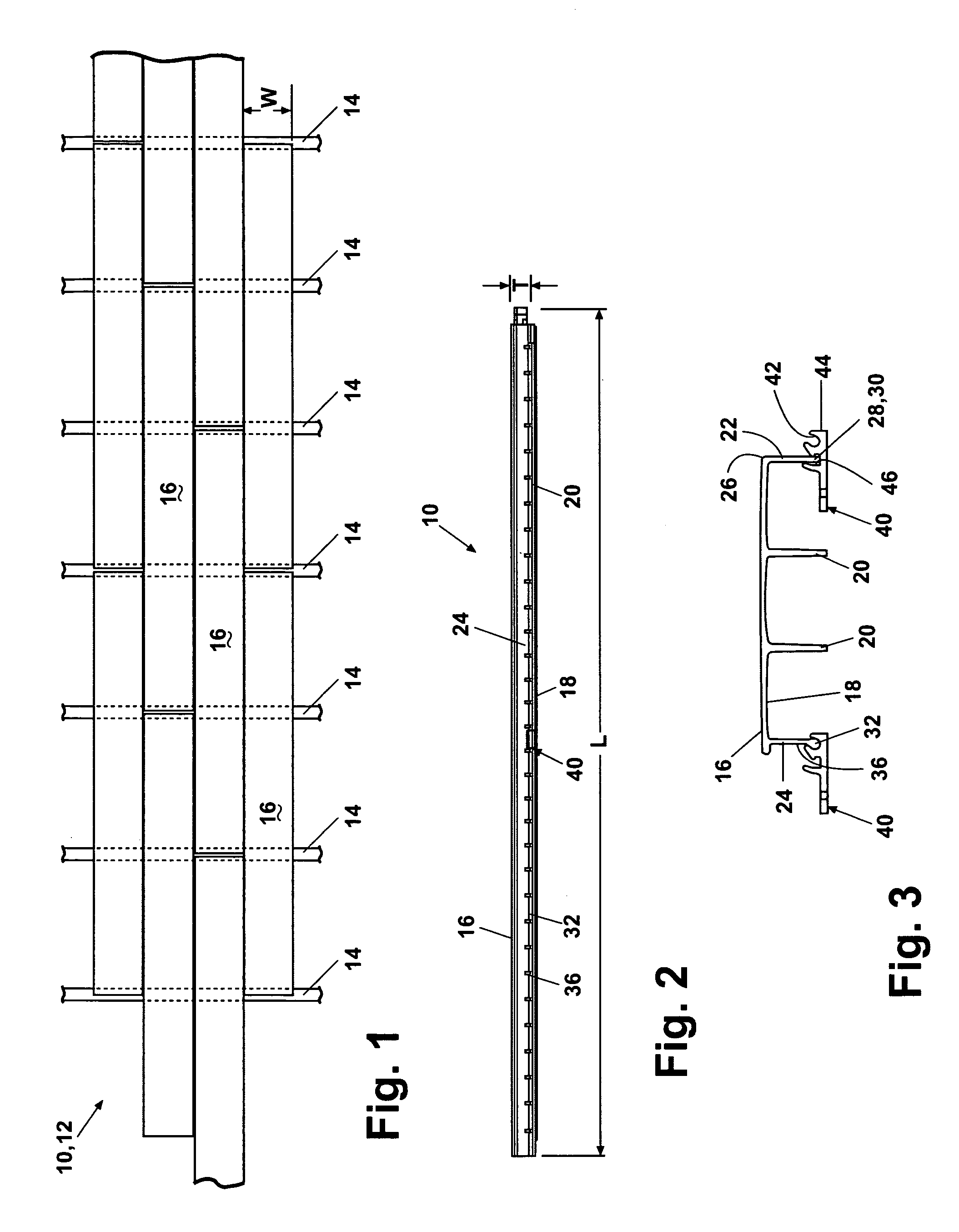
[0022]For purposes of the following description, the terms “upper,”“lower,”“left,”“rear,”“front,”“vertical,”“horizontal” and derivatives of such terms shall relate to the invention as oriented in FIGS. 2 and 3. However, it is to be understood that the invention may assume various alternative orientations, except where expressly specified to the contrary. It is also to be understood that the specific devices and processes illustrated in the attached drawings, and described in the following specification are simply exemplary embodiments of the inventive concepts defined in the inventive concepts of this invention. Specific dimensions and other physical characteristics relating to the embodiments disclosed herein are not to be considered as limiting unless expressly stated otherwise.

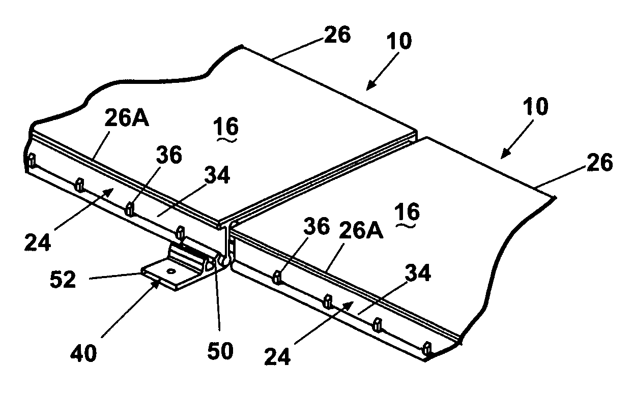
[0023]The instant invention comprises an improved decking and flooring material in the form of three dimensional tabular sheets or planks 10 having a length substantially greater than its width which in tur...


PUM

PropertyMeasurementUnit
heightaaaaaaaaaa
widthaaaaaaaaaa
distanceaaaaaaaaaa

Abstract

A floor panel and method of manufacturing wherein each panel comprises a sheet having at least two stiffening members extending from the lower surface and substantially the length of the sheet. A bead is defined along one of the stiffening members while a tab is defined along the other stiffening member. Clips are provided to fasten the bead and tab in a locking relationship to hold the sheet in position. A flange formed at one end of the panel is received within a recess formed at an opposite end of another panel to automatically space one panel from another.

Description

CROSS REFERENCE TO RELATED APPLICATION[0001]This application claims priority of U.S. Provisional Patent Application No. 60 / 469,477 filed 9 May 2003, the contents of which are incorporated herein by reference.BACKGROUND OF THE INVENTION[0002]1. Field of the Invention[0003]This invention relates to building materials. In particular, the invention concerns an improved panel system, and more particularly the invention relates to a panel system for use as flooring or decking.[0004]2. Discussion of the Related Art[0005]Traditionally, building materials consist of various forms of natural resources, such as stone, wood, and clay. More recently, man-made materials have been introduced. There has been an increase on the demand for man-made materials substituting polymeric materials for wood products. Certain companies have combined a mixture of polymers and wood chips and / or dust and extruded this mixture to form long planks. Once cured, these planks have been used as decking materials and a...

Claims


Application Information

Patent Timeline
Patent Type & Authority Patents(United States)
IPC IPC(8): F16D1/00E04B2/30E04B5/00E04F15/10
CPCE04F15/10Y10T403/7094E04F2201/0594E04F2201/0517F16B2200/30
Inventor SCHROTENBOER, RICHARD L.
Owner JIMDI
Why Eureka
Try Eureka