Vector wind sensor and integrated antenna

a wind sensor and antenna technology, applied in the field of wind sensors and integrated antennas, can solve the problems of little power and achieve the effect of convenient transport and portability

Inactive Publication Date: 2010-06-08
HONEYWELL INT INC
View PDF5 Cites 23 Cited by
  • Summary
  • Abstract
  • Description
  • Claims
  • Application Information

AI Technical Summary

Benefits of technology

[0009]In accordance with other aspects of the invention, the elongated vertical member is insulated from the base by a bushing to allow the elongated vertical member to be used as a vertical antenna for a transmitter or transceiver for a datalink radio. The elongated vertical member can be made from a variety of materials, for example, but not limited to stainless steel or copper. The elongated vertical member can be telescopic, fixed and detachable, and / or segmented so as to ease transport and portability.
[0010]In accordance with still other aspects of the invention, a tilt sensor is positioned on the sensor plate to measure deviation of the elongated vertical member from true vertical for the installation and compensation of the load sensor measurements. Measurements from the tilt sensor can be used to mathematically compensate and correct for deviations of the anemometer assembly, and by extension the elongated vertical member housed therein, from a true vertical position. As a result, counterpoising mechanisms are not necessary, and the sensor plate does not have to be perfectly level when in operation.
[0011]In accordance with still other aspects of the invention, an antenna lead connects the elongated vertical member to a datalink radio that can link to a remote computer system. The data can be transmitted to a remote location where it can reduce the raw data from the load sensors to calculate wind velocity and wind direction.

Problems solved by technology

A wind sensor measures relative wind speed and wind direction without the use of moving parts and consumes very little power making it suitable for unattended operation.

Method used


Image

  • Vector wind sensor and integrated antenna
  • Vector wind sensor and integrated antenna
  • Vector wind sensor and integrated antenna

Examples


Embodiment Construction

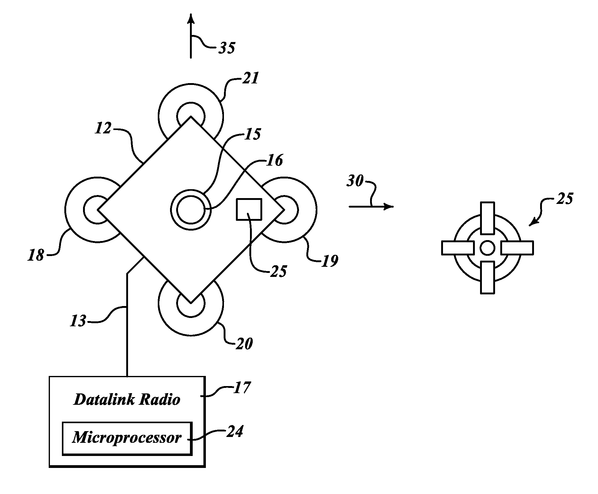
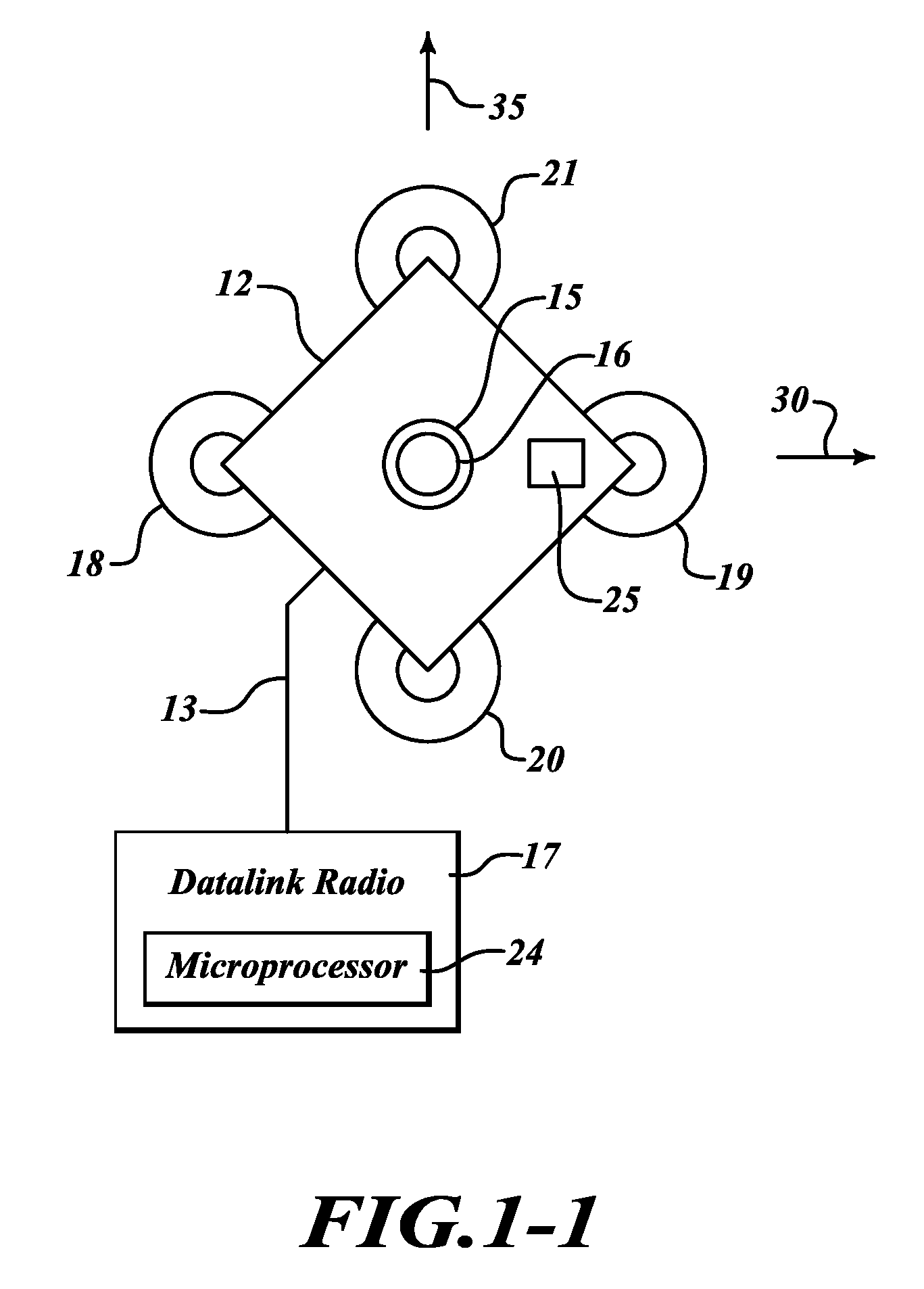
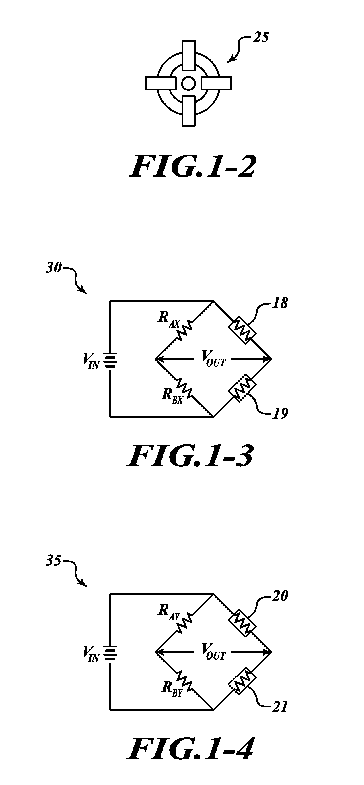
[0018]FIG. 1-1 and FIG. 1-2 shows a schematic top view of an exemplary embodiment of a an anemometer assembly 10 of the present invention, that includes a plurality of opposing load sensors 18 and 19 located on an X-axis 30, and load sensors 20 and 21 located on an Y-axis 30, a sensor plate 12; a main wind sensor that is an elongated vertical member / antenna 16; an insulating bushing 15, an antenna lead 13, a tilt sensor 25 (FIG. 1-2), and a datalink radio 17 having a microprocessor 24. The tilt sensor 25 (FIG. 1-2) is positioned on the sensor plate 12 to detect the angle of inclination of the device and generate correction data. The load sensors 18-21 are connect at corners of the sensor plate 20 and a base structure (FIG. 2). The load sensors 18-21 are in signal communication with the datalink radio 17.

[0019]The sensor plate 12 is mounted on top of the plurality of load sensors 18, 19, 20, 21 preferably at 90 degree angles to each other, each load sensor 18, 19, 20, 21 positioned a...


PUM


Abstract

An anemometer assembly for sensing and transmitting wind speed and wind direction data. The wind sensor measures relative wind direction and wind speed without the use of moving parts and consumes very little power making it suitable for unattended operation. The main wind sensing member is an elongated vertical member that can be used as radio antenna. The data can be transmitted from a remote location and thus relay data to a central collection repository or network location.

Description

BACKGROUND OF THE INVENTION[0001]Anemometers are primarily used to measure air flow and commonly comprise a rotating element whose angular speed of rotation is correlated with the linear velocity of the air flow. Cup and vane anemometers are by far the most prevalent. The cups typically spread over 120 degree angles, attached at a central hub. The center of the hub translates rotational movement along a vertical axis when the cups respond to air movement in the horizontal plane. The rotational movement relates to the speed of the impinging air currents and thus to wind speed. One of the drawbacks of this type of anemometer is that the inertia of the mechanical mechanism must be overcome. The weather vane device requires a very free gimbal so as to allow the device to point accurately into the wind at very low wind speeds. As a result of its reliance on this mechanical element, the anemometer is not conducive to measuring gusts, and is subject to errors in measurement due to overshoo...

Claims


Application Information

Patent Timeline
Patent Type & Authority Patents(United States)
IPC IPC(8): G01P5/00
CPCG01P13/02G01P5/02
Inventor CORNETT, ALANBECKER, ROBERT CHARLESDREXLER, JEROME PAUL
Owner HONEYWELL INT INC
Why Eureka
Try Eureka