
Electric generator and process for assembling a wind turbine equipped with the generator

a technology of electric generator and wind turbine, which is applied in the direction of electric generator control, machines/engines, mechanical equipment, etc., can solve the problems of high overall assembly weight, complicated road and/or railway transportation and onsite assembly, and the inability to assemble the generator in the wind turbine. to achieve the effect of easing generator transportation and assembly

Inactive Publication Date: 2014-04-22
NORDEX ENERGY SPAIN SA
View PDF7 Cites 0 Cited by
  • Summary
  • Abstract
  • Description
  • Claims
  • Application Information

AI Technical Summary

Benefits of technology

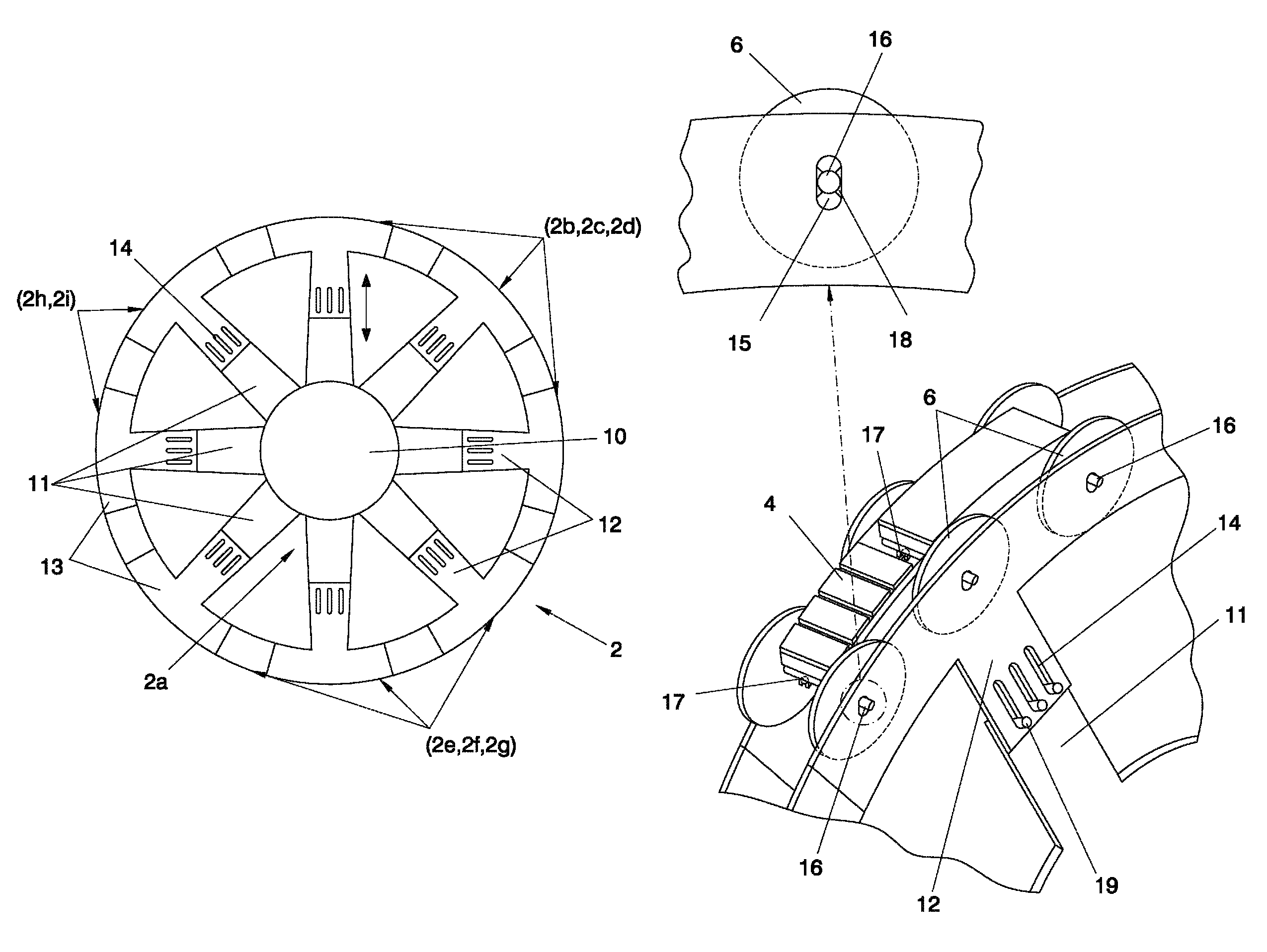
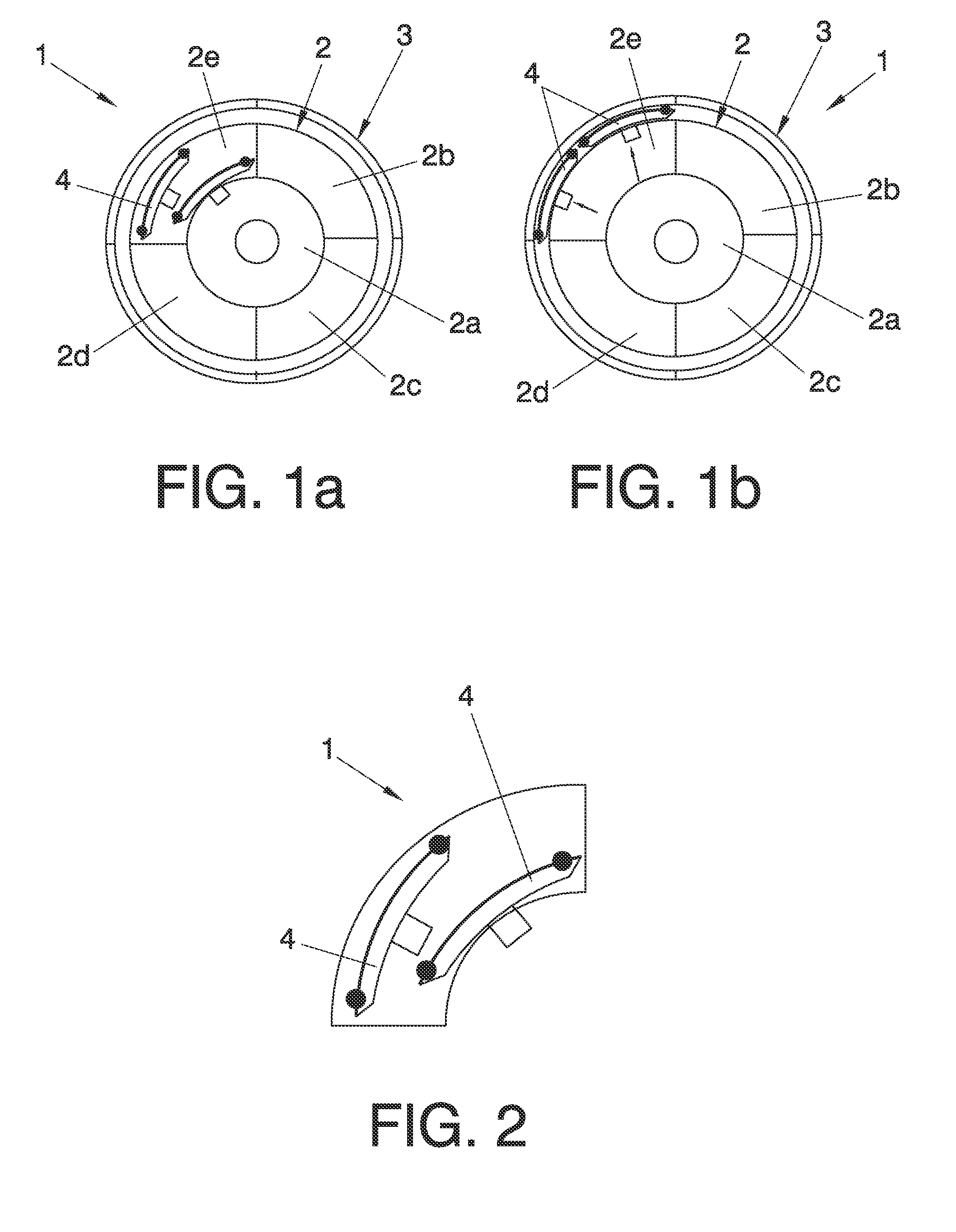
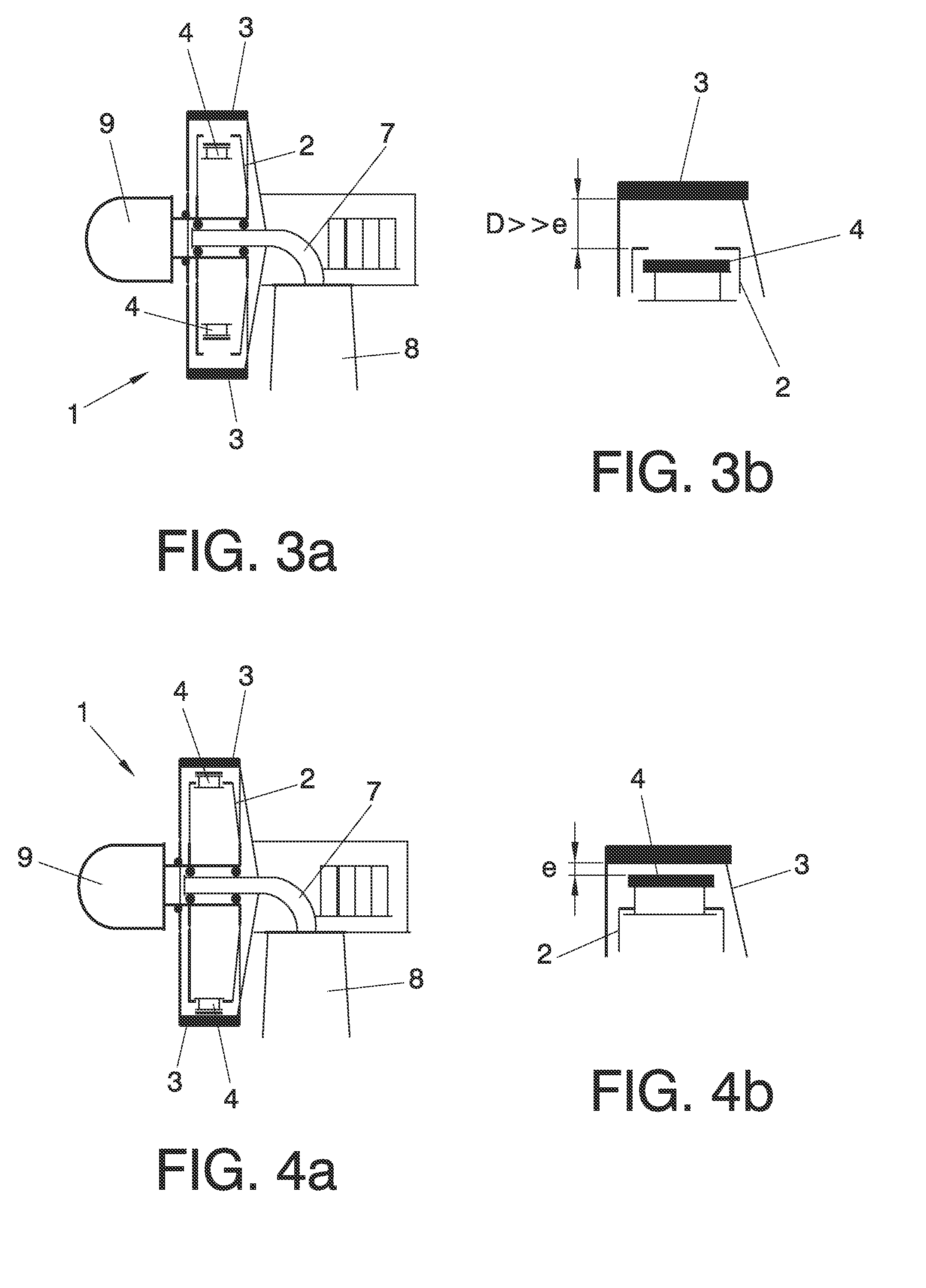
[0001]The object of the present invention is a generator having a rotor which comprises rotor excitation element-carrying modules, for example magnets, radially movable in relation to the generator shaft in such a manner, when in their retracted position, as to significantly ease generator transport and assembly. The use of these movable magnet-carrying modules is particularly useful in direct drive-type generators which do not require a multiplier.

Problems solved by technology

This implies that the dimensions of a direct drive electric generator are often much larger than those of conventional generators, which complicates road and / or railway transport and onsite assembly.
Consequently, in order to guarantee minimum and constant gap width, one of the most frequent solutions in generator structure design has been to give it great rigidity, resulting in very high overall assembly weight.
However, assembly thereof in the wind turbine is not resolved by the proposed design.
Additionally, with this solution the connections must be made at height, increasing the difficulty and therefore the time required for this type of operation.
The main drawback of the aforementioned method, particularly in the case of magnet rotors, is the difficulty of the operation due to the forces of attraction between said magnets and the magnetic material of the stator, in this case laminated steel, added to the complexity of performing said process at height.
As mentioned earlier, another major challenge in a multi-megawatt wind turbine equipped with a large-sized electric generator is minimising gap width and ensuring that the dimensions do not vary substantially during operation without substantially increasing the rigidity of the electric generator structure, which would imply an increase in the weight and cost of the structural part thereof and, consequently, an increase in the rest of the structural parts of the wind turbine (frame, tower, etc.).
The main drawback is the existence of a single bearing for both the wind rotor and the electric generator rotor.
This causes all the loads and vibrations to be transmitted to the stator structure which, therefore, must be dimensioned so as to support it, guaranteeing adequate dimensional gap tolerances, with the ensuing increase in material and cost.

Method used


Image

  • Electric generator and process for assembling a wind turbine equipped with the generator
  • Electric generator and process for assembling a wind turbine equipped with the generator
  • Electric generator and process for assembling a wind turbine equipped with the generator

Examples


Embodiment Construction

[0011]According to a first aspect of the invention, the inventors of the present application have developed a novel electric generator, preferably of the direct drive-type, the rotor of which is formed by a structure whereto a plurality of rotor excitation element-carrying modules are coupled, for example magnets, said rotor excitation element-carrying modules being radially movable in relation to the central shaft of the generator. In the present patent, the term “radially movable” relates to movements having a significant radial component, even if combined with axial or tangential components. In fact, in the example that will be described in detail hereunder, the magnet-carrying modules have a circumferential sector shape and, therefore, in order to dispose these in a retracted position while preventing certain elements from coming into contact with adjacent elements, axial and tangential movements must be combined. In any case, the main concept is that the radial movement compone...


PUM

PropertyMeasurementUnit
diameteraaaaaaaaaa
sizeaaaaaaaaaa
widthaaaaaaaaaa

Abstract

A generator having a rotor which comprises rotor excitation element-carrying modules, for example magnets, radially movable in relation to the generator shaft in such a manner, when in their retracted position, as to significantly ease generator transport and assembly. The use of these movable magnet-carrying modules is particularly useful in direct drive-type generators which do not require a multiplier. Another object of the invention is an assembly process which comprises a generator equipped with the radially movable magnet-carrying modules.

Description

OBJECT OF THE INVENTION[0001]The object of the present invention is a generator having a rotor which comprises rotor excitation element-carrying modules, for example magnets, radially movable in relation to the generator shaft in such a manner, when in their retracted position, as to significantly ease generator transport and assembly. The use of these movable magnet-carrying modules is particularly useful in direct drive-type generators which do not require a multiplier.[0002]Another object of the invention is a process for assembling a wind turbine which comprises a generator equipped with said radially movable rotor excitation element-carrying modules.BACKGROUND OF THE INVENTION[0003]Up until now, most wind turbines used a multiplier to increase the rotation speed of the shaft coupled to the generator. However, the current trend in the manufacture of wind turbines with increasingly higher power output is to suppress the multiplier in the power conversion system, with the object o...

Claims


Application Information

Patent Timeline
Patent Type & Authority Patents(United States)
IPC IPC(8): F03D9/00
CPCH02K15/00H02K2213/09H02K7/1838H02K1/278Y02E10/725H02K15/16H02K7/088H02K2201/03H02K15/03Y02E10/72H02K21/02Y10T29/49009
Inventor AZANZA LADRON, EDUARDOGARCIA SAYES, JOSE MIGUELARLABAN GABEIRAS, TERESAN NEZ POLO, MIGUEL
Owner NORDEX ENERGY SPAIN SA
Learn More