Open-flow vertical wind generator

a technology of open-flow and wind generator, which is applied in the direction of machines/engines, renewable energy generation, greenhouse gas reduction, etc., can solve the problems of large turbines that require additional, high-strength structural components, and the force of wind acting on the rotary vanes is dramatically reduced by the closed flow of such designs, so as to achieve easy transportation, low weight, and high strength.

Inactive Publication Date: 2013-11-26
MAYNARD MARK
View PDF5 Cites 15 Cited by
  • Summary
  • Abstract
  • Description
  • Claims
  • Application Information

AI Technical Summary

Benefits of technology

[0020]Consequently, there is a need for a high strength, low weight, easily transportable vertical win

Problems solved by technology

However, where no suction forces are generated on down stream faces of the stators, the closed flow of such designs dramatically diminishes the force of the wind acting upon the rotary vanes.
Unfortunately, such large turbines raise transportation costs beyond 30 percent of overall costs because they must be transported as wide-loads, or on trains having limited access, or be

Method used


Image

  • Open-flow vertical wind generator
  • Open-flow vertical wind generator
  • Open-flow vertical wind generator

Examples


Embodiment Construction

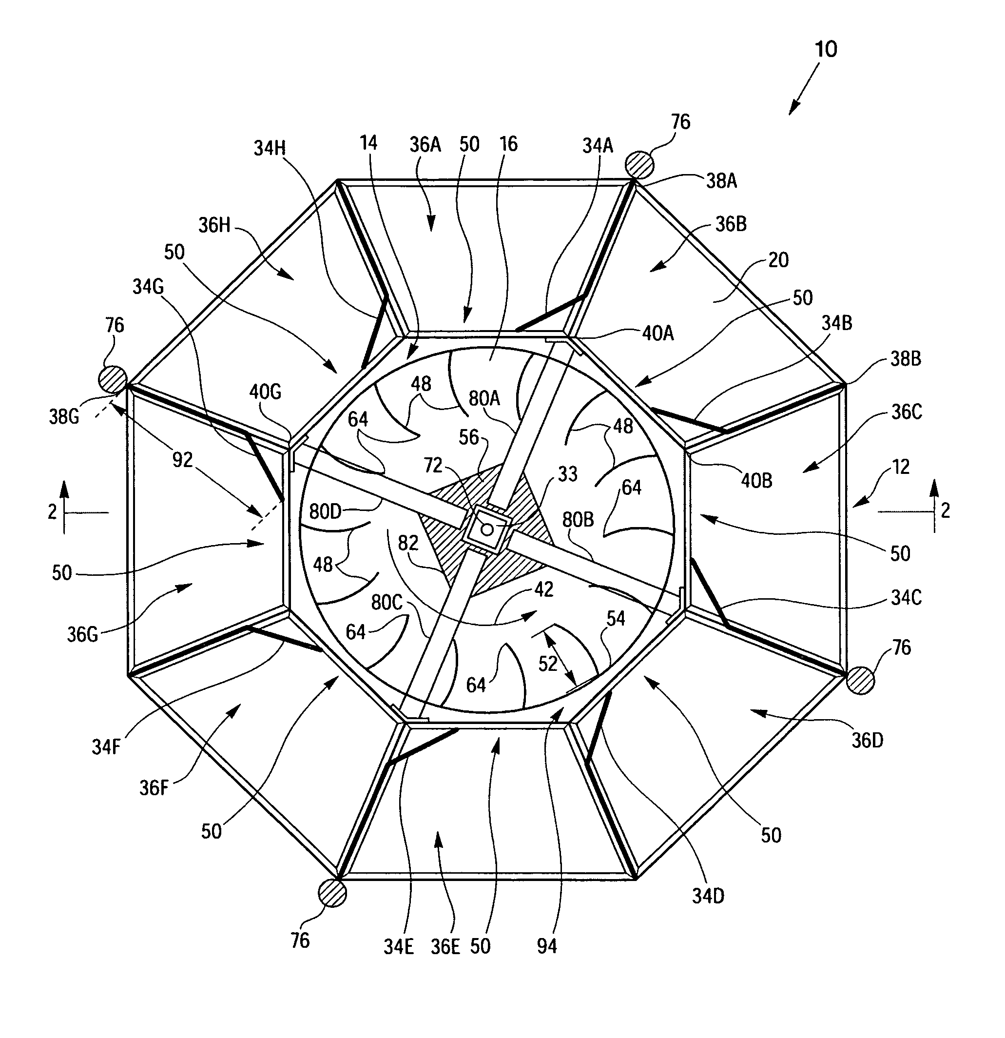
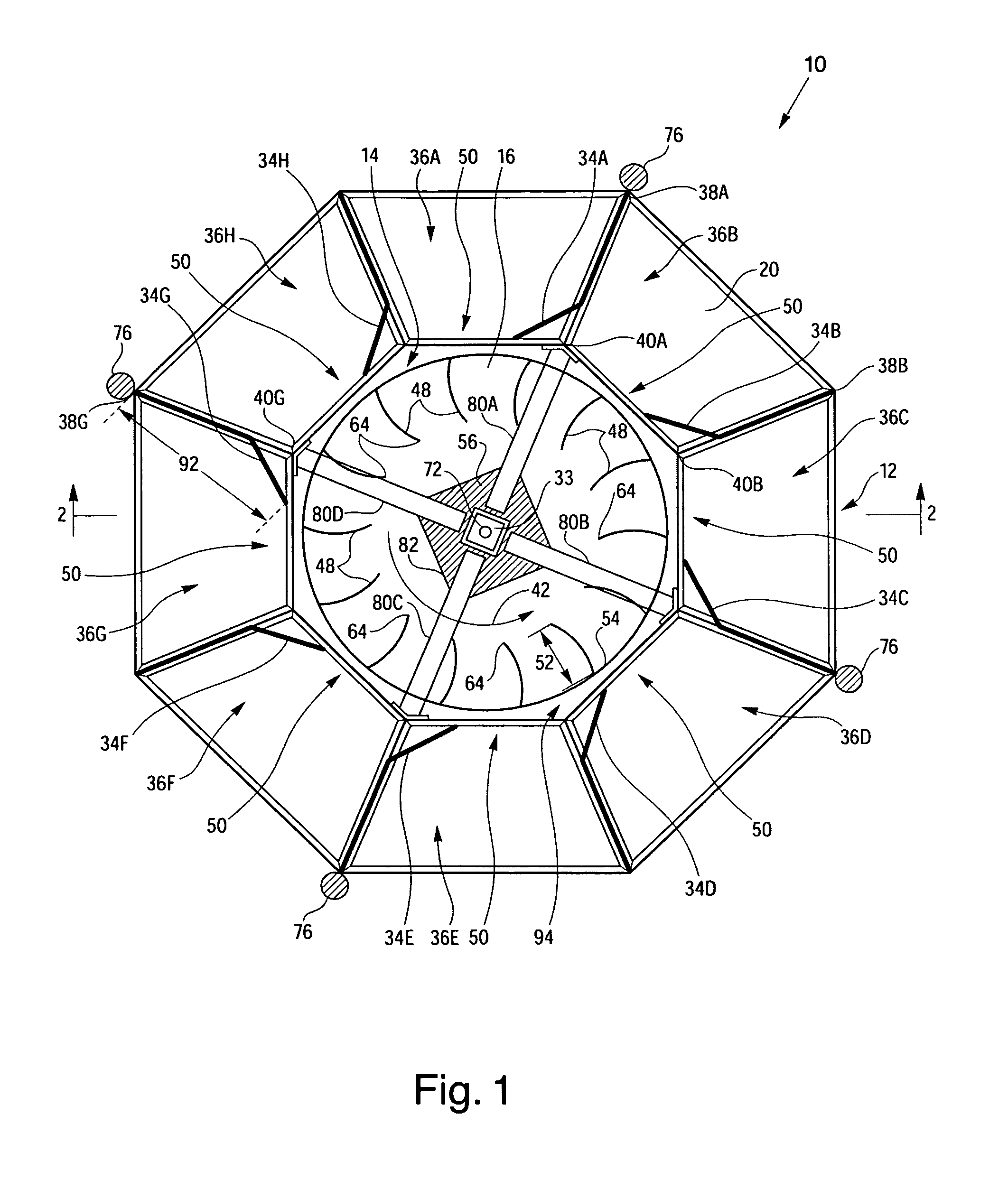
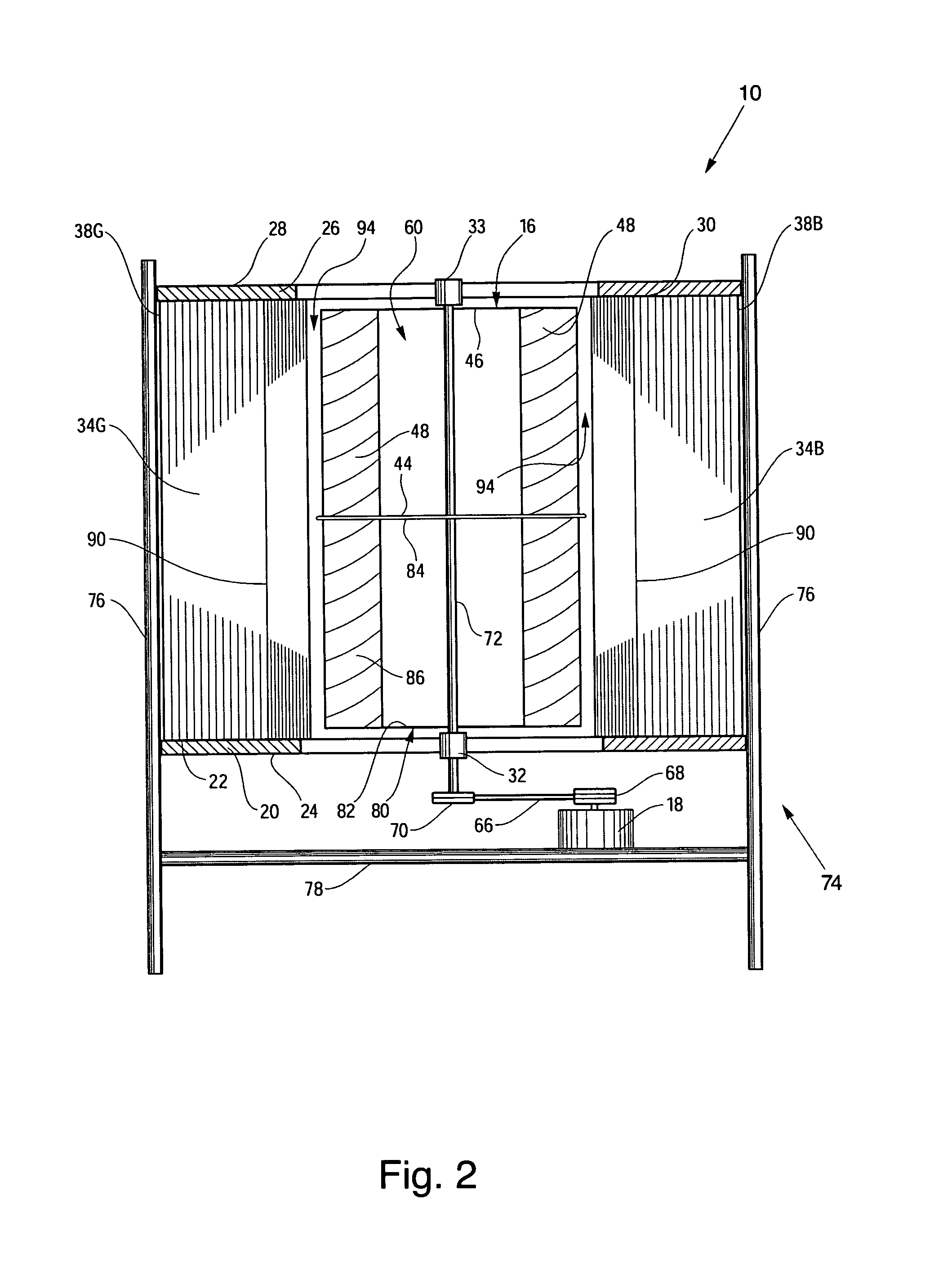
[0026]Referring to the drawings in detail a top plan view of an open-flow vertical wind generator for generating electricity is shown in FIG. 1, and is generally designated by the reference numeral 10. The open-flow vertical wind generator 10 includes an essentially cylindrical stator assembly 12 defining a central turbine void 14 in which a wind turbine 16 rotates to mechanically rotate an electrical generator 18 (shown only in FIG. 2).

[0027]As shown best in FIGS. 1 and 2, the stator assembly 12 includes a base truss 20 having a top surface and an opposed bottom surface 24, and upper truss 26 having a top surface 28 and opposed bottom surface 30. The bottom truss 20 may also include a bottom bearing 32, and the top truss may include a top bearing 33. A plurality of stators 34A, 34B, 34C, 34D, 34E, 34F, 34G, 34H (“34A-34H”) are secured to and extend between the top surface 22 of the base truss 20 and the bottom surface 30 of the upper truss 26. In a preferred embodiment, the stators...


PUM


Abstract

The generator (10) includes an essentially cylindrical stator assembly (12) defining a central turbine void (14) in which a wind turbine (16) rotates to power an electrical generator (18). The wind turbine (16) includes vanes (48) having a width (52) less than 25 percent of a diameter (58) of the turbine (16). The turbine (16) defines an open void (60) between the vanes (48) for unrestricted passage of air through the wind turbine (16). Non-planar stators (34A-34H) extend between a base and an upper truss (20, 26) to strengthen the stator assembly (12) and to direct air exiting directional ducts (36A-36H) to move in a first rotational direction (42) within the turbine void (14). A plurality of geodesic truss segments (96A-96H) form the base and upper trusses (20, 26) to produce a strong, light-weight wind generator (10) that is easily assembled on-site.

Description

CROSS REFERENCE TO RELATED APPLICATION[0001]This Application claims the benefit of U.S. Provisional Patent Application Ser. No. 61 / 274,855 that was filed on Aug. 21, 2009, entitled “Self-Regulating Vertical Wind Turbine”.DESCRIPTION[0002]This disclosure relates to wind generators for generating electricity and in particular relates to an open-flow vertical wind generator that utilizes structural features to enhance structural integrity, ease of manufacture and assembly, and efficiency of operation of the generator.BACKGROUND ART[0003]It is known that wind generators are increasingly used for non-polluting production of electricity. Most wind generators utilize spinning blades similar to an airplane propeller supported on a post high above any buildings or nearby tree line. The resulting rotational force on an axle of the blade-type of wind generator or turbine rotates the axle about an axis horizontal to the ground or support surface to generate electricity. These wind generators ne...

Claims


Application Information

Patent Timeline
IPC IPC(8): F03D3/00
CPCF03D3/00F03D3/0409Y02B10/30Y02E10/74F03D15/10F03D3/0427F03D9/25
Inventor MAYNARD, MARK
Owner MAYNARD MARK
Why Eureka
Try Eureka