Structure of speaker

a speaker and structure technology, applied in the direction of transducer details, electrical transducers, plane diaphragms, etc., can solve the problem of limited voice of the generated sound, and achieve the effect of convenient manufacturing and assembly, loud sound, and sufficient winding spa

Inactive Publication Date: 2005-06-09
DELTA ELECTRONICS INC
View PDF1 Cites 14 Cited by
  • Summary
  • Abstract
  • Description
  • Claims
  • Application Information

AI Technical Summary

Benefits of technology

[0015] One of the advantages of the speaker structure of the invention is the ease of manufacturing and assembly. Besides, the coil has sufficient winding space, and does not break during operation process. Furthermore, the magnetic force derived can generate loud sound and the vibration level of the magnetic assembly is uniform. Also, the speaker structure is adaptable to large-scale and micro-scale speaker.

Problems solved by technology

Therefore, the voice of the generated sound is limited.

Method used


Image

  • Structure of speaker
  • Structure of speaker
  • Structure of speaker

Examples


Embodiment Construction

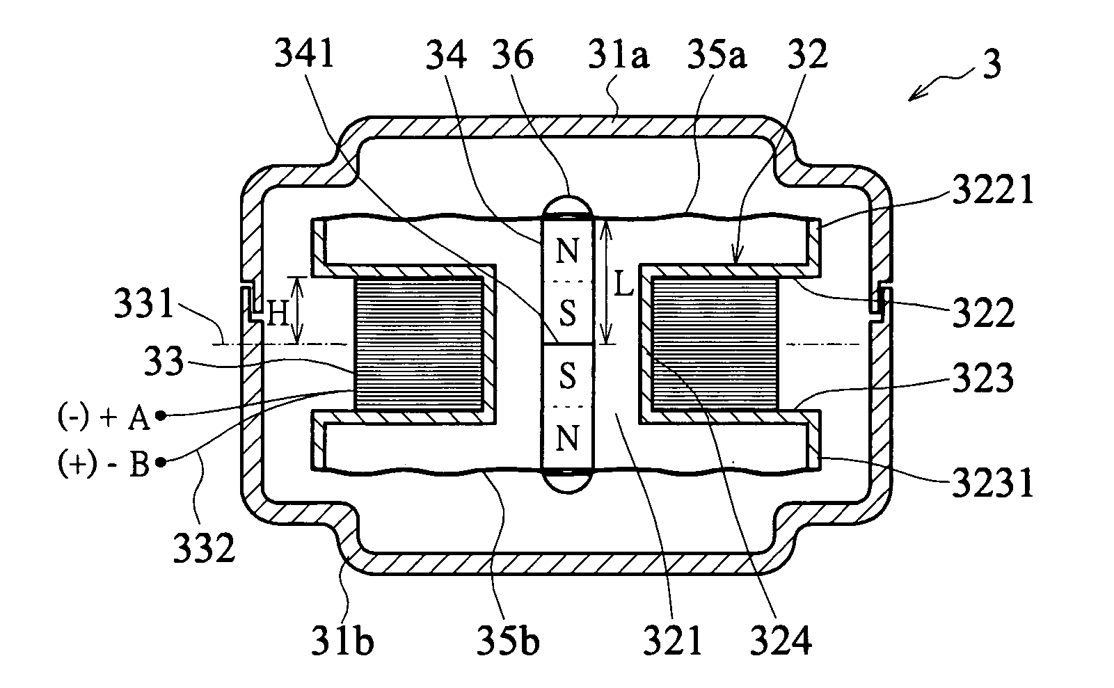
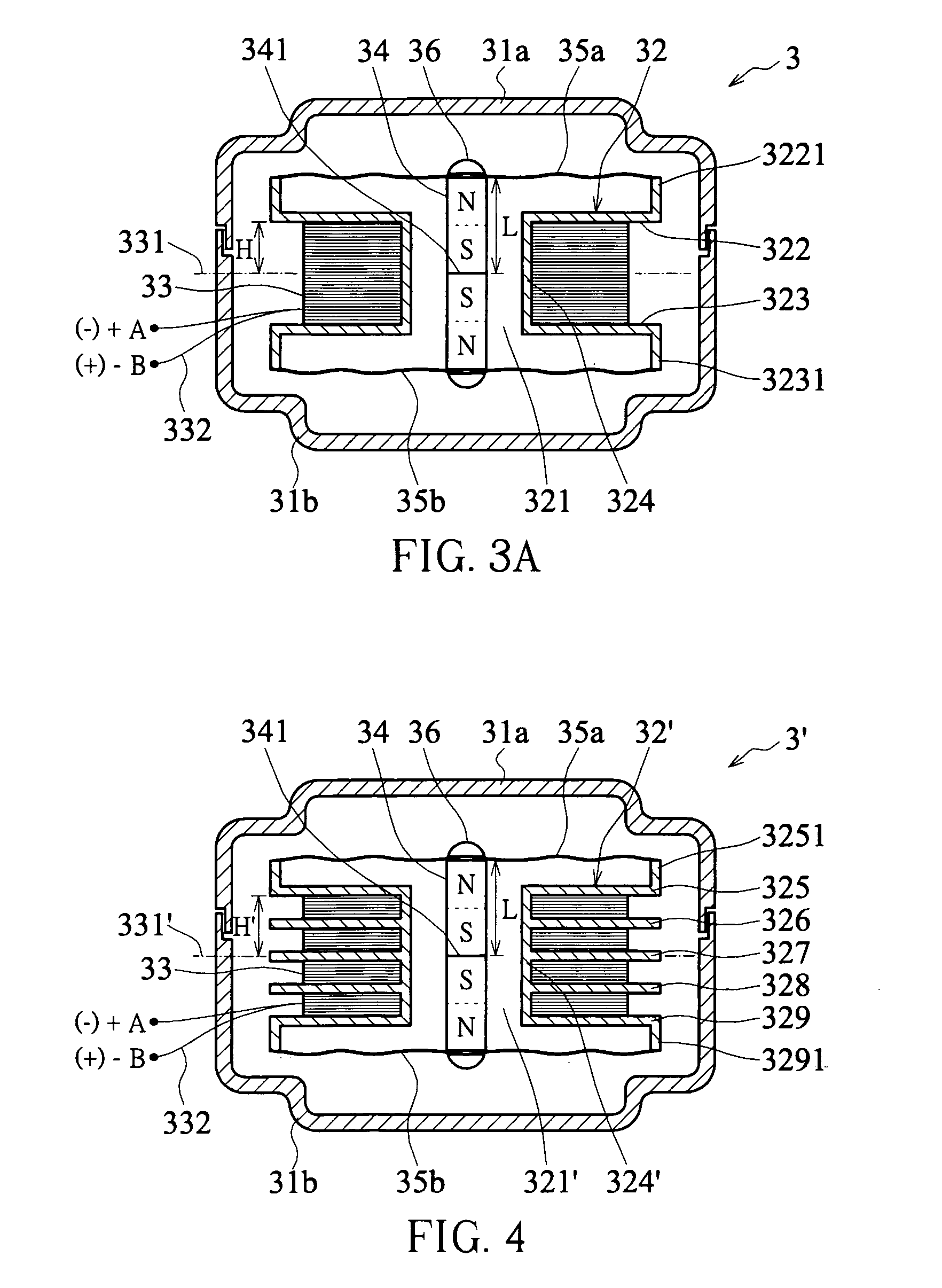
[0022] As shown in FIG. 3A, a speaker structure 3 of the first embodiment of the invention includes an upper housing 31a and lower housing 31b, a bobbin 32, a coil 33, a magnetic assembly 34 and two membranes 35a and 35b. The upper housing 31a, lower housing 31b, and the bobbin 32 are made of plastics. The magnetic assembly 34 can be made from materials such as permanent magnet or other materials with magnetism such as plastic magnet.

[0023] The bobbin 32 has a through hole 321 and two partition surfaces 322 and 323 extending outwardly in radial from the outer side surface 324. Furthermore, the partition surfaces 322 and 323 extend upwards and downwards to form flanges 3221 and 3231, respectively. The coil 33 is wound on the outside surface 324 of the bobbin 32 and between the two partition surfaces 322 and 323. Furthermore, two external wires 332 are extracted from the coil 33 to be connected to an external power supply. Two membrane 35a and 35b are disposed at upper and lower ends...


PUM


Abstract

A structure of speaker is disclosed. The disclosed speaker structure includes at least a bobbin, a coil, a membrane, and a magnetic assembly. The coil is wound around the side surface of the bobbin, and the membrane is disposed at end of the bobbin. Besides, the magnetic assembly is suspended in a through hole of the bobbin and have one end adhered to the membrane.

Description

BACKGROUND OF THE INVENTION [0001] 1. Field of the Invention [0002] This invention relates to a sound generating device and, more particularly, to an improved structure of speaker. [0003] 2. Description of Related Art [0004] In the development of various audio and video multimedia devices, the quality of audio signal is improving as well as that of video signals day by day. Notwithstanding the current technology can integrate magnificent sound signals, superior sound quality still needs a good speaker to perform. Since the sound of a multimedia audio and video equipment is produced by transforming an electric signal into a sound wave via a speaker, the speaker need to be improved to obtain sound signals in high quality. [0005] As shown in FIG. 1, a conventional speaker 1 has an upper cover 11, a base 12, a permanent magnet 13, a coil 14 and a membrane 15. The permanent magnet 13 is mounted in a notch 121 of the base 12 with the poles distributed as shown in the diagram (N-pole on th...

Claims


Application Information

Patent Timeline
Patent Type & Authority Applications(United States)
IPC IPC(8): H04R1/00H04R1/02H04R1/20H04R9/06H04R7/04H04R9/02H04R9/04H04R11/02
CPCH04R11/02
Inventor CHEN, LEE-LONGWU, CHEN-FENGYEH, MING
Owner DELTA ELECTRONICS INC
Why Eureka
Try Eureka