Endless belt conveyor frame and tensioning device including center drive construction

a technology of tensioning device and conveyor frame, which is applied in the direction of conveyor parts, rollers, transportation and packaging, etc., can solve the problems of inability to provide belt tracking, laborious and time-consuming task of threading conveyor belt through the center drive unit, and limited conveyor width, so as to reduce the number of components, and improve the effect of assembly and operation

Inactive Publication Date: 2005-07-07
DORNER MFG. CORP.
View PDF13 Cites 21 Cited by
  • Summary
  • Abstract
  • Description
  • Claims
  • Application Information

AI Technical Summary

Benefits of technology

[0015] The bed plate strips are attached to the cross members by connectors or fasteners, preferably in the form of self-tapping screws. The center slot formed in each cross member allows the bed plate strips to be attached anywhere along the length of the cross member, thereby allowing the conveyor frame to be formed by simply cutting the cross members to the desired width and attaching the bed plate strips.
[0025] The various features of the invention can be separately incorporated into a conveyor structure, and each provides certain advantages, such as reduction in the number of components, strength of the conveyor frame, or ease of manufacture, assembly and operation. In a particularly preferred form, the features are employed in combination to provide a conveyor construction which involves significant improvement in components, assembly and operation. Various other features, objects and advantages of the invention will be made apparent from the following description taken together with the drawings.

Problems solved by technology

This drawback requires additional set-up time each time the belt needs to be retensioned, which is a clear drawback in the conveyor system.
Thus, the conveyor widths are limited due to the top plate configuration.
While this type of construction has been found to be highly satisfactory, it suffers several drawbacks, including the inability to provide belt tracking and the requirement of a conveyor belt having a center rib that is received within the groove formed in the top plate.
Although the center drive unit illustrated in the '447 patent is efficient for driving the conveyor belt, threading the conveyor belt through the center drive unit is a tedious and time-consuming task.
Further, the multiple spindles require additional parts and manufacturing costs to produce.

Method used


Image

  • Endless belt conveyor frame and tensioning device including center drive construction
  • Endless belt conveyor frame and tensioning device including center drive construction
  • Endless belt conveyor frame and tensioning device including center drive construction

Examples


Embodiment Construction

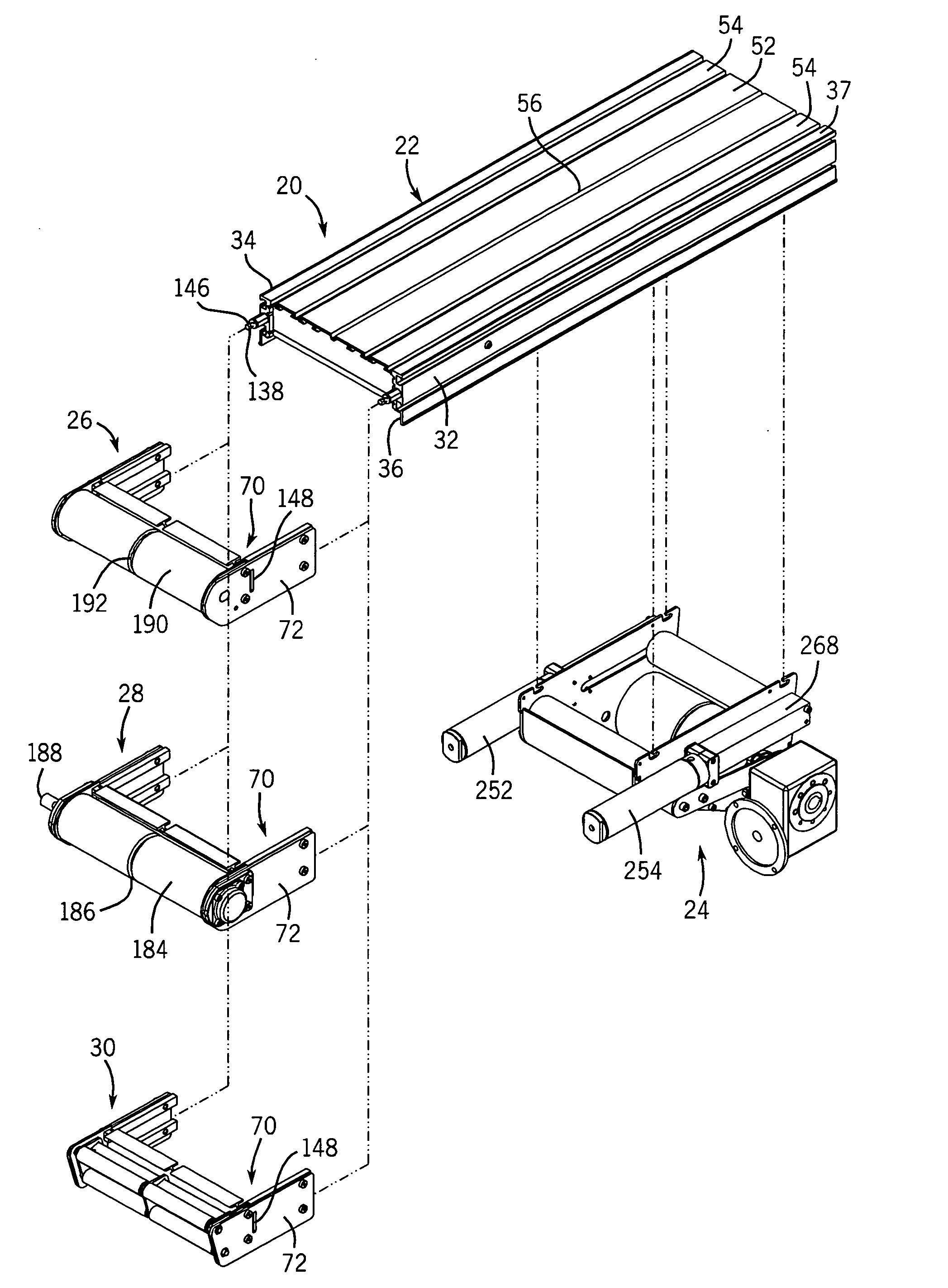
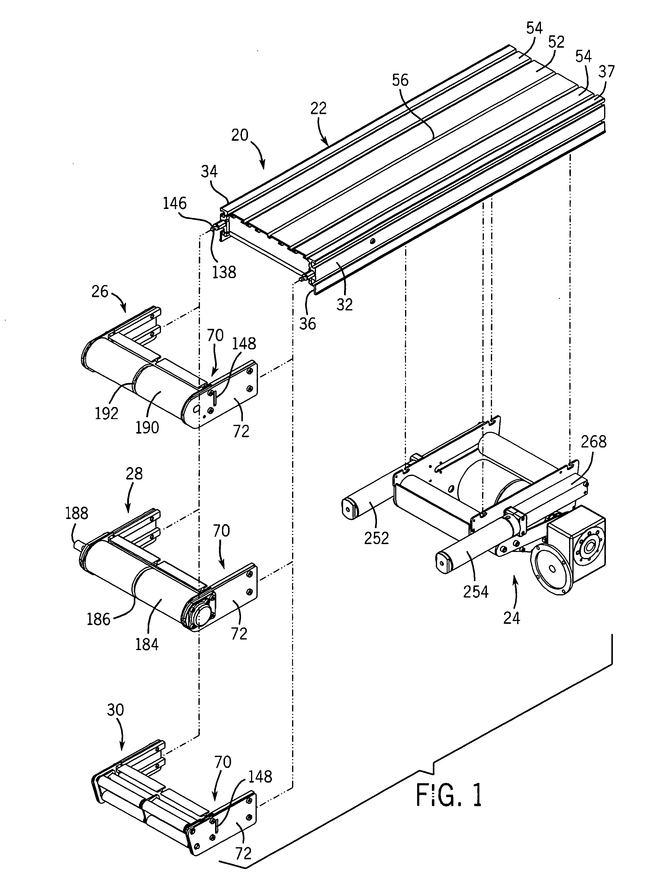
[0051]FIG. 1 illustrates a conveyor assembly 20 constructed in accordance with the present invention. Generally, the conveyor assembly 20 includes a conveyor frame assembly 22, a center drive assembly 24 and either a tensioning section 26, an end drive section 28 or a transfer tail section 30. In FIG. 1, although the tensioning section 26, end drive section 28 and transfer tail 30 are illustrated as being attachable only to the first end of the conveyor frame assembly 22, it should 5 be understood that a similar arrangement can be utilized on the opposite end of the conveyor frame assembly 22. Although not shown in FIG. 1, an endless conveyor belt is mounted over the frame assembly and moved by either the center drive assembly 24 or the end drive section 28 in a conventional manner.

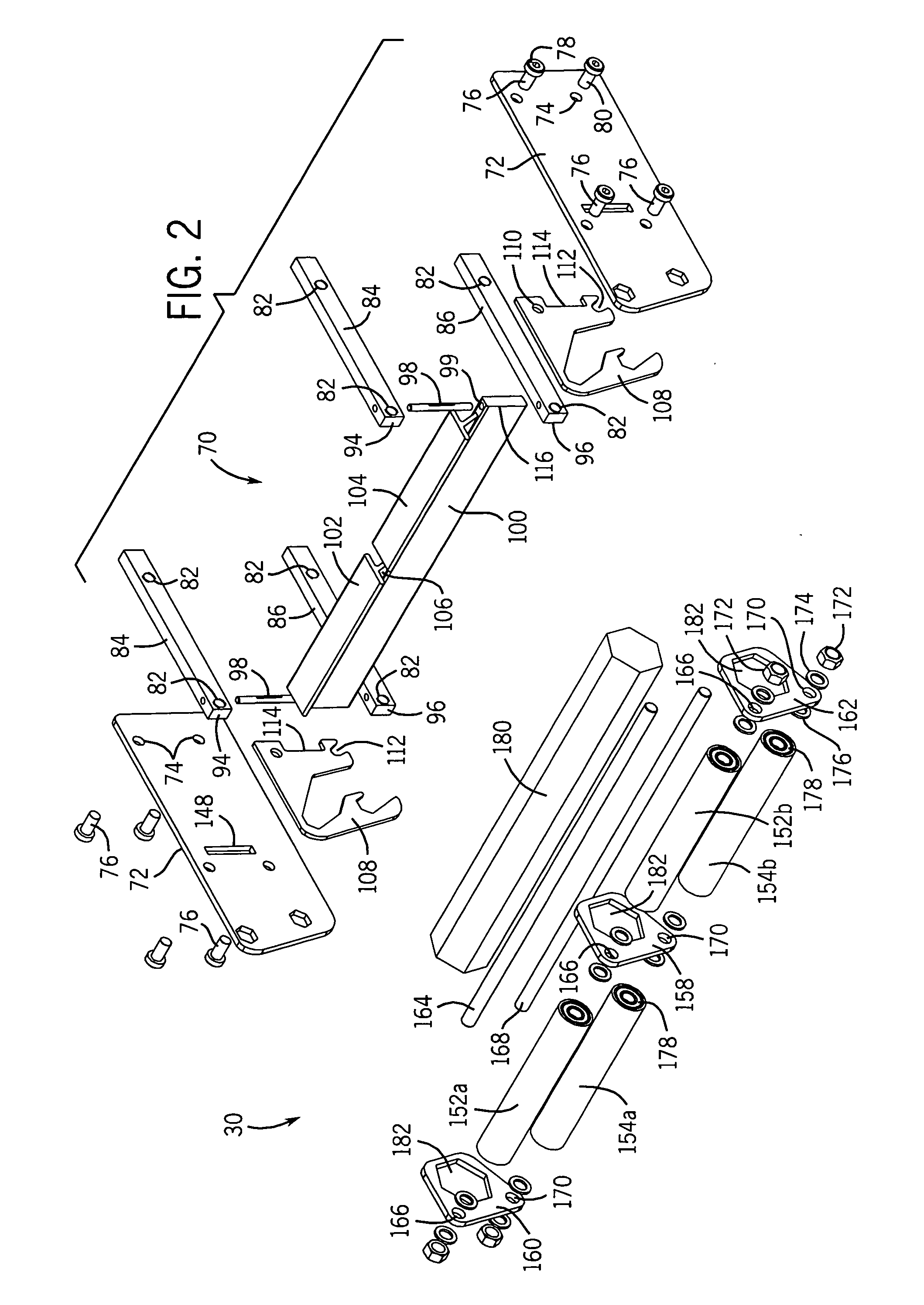
[0052] As illustrated in FIG. 1, the conveyor frame assembly 22 generally 10 includes a pair of side frame members 32, 34 that each extend between a first end 36 and a second end 37. In the preferred emb...


PUM


Abstract

A conveyor construction that includes a conveyor frame assembly formed from a pair of spaced side frame members interconnected with each other by spaced cross members. The upper bed of the conveyor frame assembly is formed from individual bed plate strips attached to each of the cross members. The width of the conveyor frame assembly can be modified by the proper selection of the number of bed plate strips. The conveyor frame assembly includes a separate tensioning assembly and tracking adjustment assembly. The tracking adjustment assembly is adjusted separate from the tensioning assembly such that additional tension applied to the conveyor belt does not affect the previously selected tracking adjustment. The conveyor construction includes a center drive unit having only a single drive roller, a guide roller and a tensioning roller. The tensioning roller position is controlled by a pair of spaced tensioning cylinder.

Description

CROSS-REFERENCE TO RELATED APPLICATION [0001] The present invention is based on and claims priority to U.S. Provisional Patent Application Ser. No. 60 / 368,957 filed on Mar. 29, 2002.BACKGROUND OF THE INVENTION [0002] The present invention generally relates to endless belt conveyors. More specifically, the present invention relates to an endless belt conveyor having a modular frame, an improved tension and tracking mechanism and a center drive construction that increases the ease with which the conveyor belt can be removed and replaced. [0003] Known constructions of an endless belt conveyor typically includes a frame assembly, a pair of head plates located at each end of the frame assembly, a spindle extending between each pair of head plates, and a conveyor belt engaged between the spindles. One of the spindles is drivingly interconnected with a motor for rotating the spindle to impart movement to the endless conveyor belt. The drive motor can be positioned at either end of the conv...

Claims


Application Information

Patent Timeline
Patent Type & Authority Applications(United States)
IPC IPC(8): B65G21/06B65G23/44B65G39/16
CPCB65G21/06B65G39/16B65G23/44
Inventor ERTEL, DANIEL E.HALL, SCOTT M.
Owner DORNER MFG. CORP.
Why Eureka
Try Eureka