Brake mechanism for curtain linkage system

Inactive Publication Date: 2006-02-23
HUANG SHIEN TE
View PDF5 Cites 18 Cited by
  • Summary
  • Abstract
  • Description
  • Claims
  • Application Information

AI Technical Summary

Benefits of technology

[0025] A confining ring is configured on a periphery of the circular box, and a rolling pin is configured between an inner circumference of a confining ring and a rotor,

Problems solved by technology

However, because the brake effect is effectuated by means of the variance in the internal diameter of the spring, when the variance exceeds a bound critical point, slippage results as a consequence.
However, because quality of the p

Method used


Image

  • Brake mechanism for curtain linkage system
  • Brake mechanism for curtain linkage system
  • Brake mechanism for curtain linkage system

Examples


Embodiment Construction

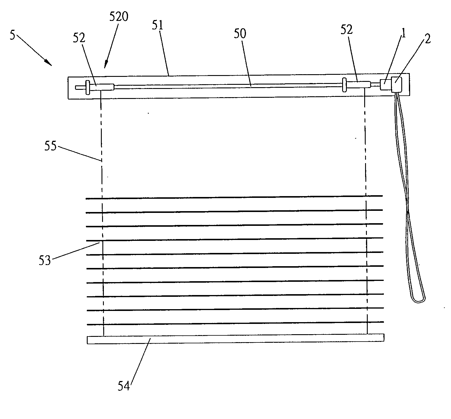
[0037] Referring to FIG. 3, which shows the present invention primarily comprising a drive unit 2 that actuates a brake mechanism 3, which is further coupled to a linkage shaft 20, and entire structural configuration of such is installed as part of a power mechanism in the aforementioned top rail of a curtain set.

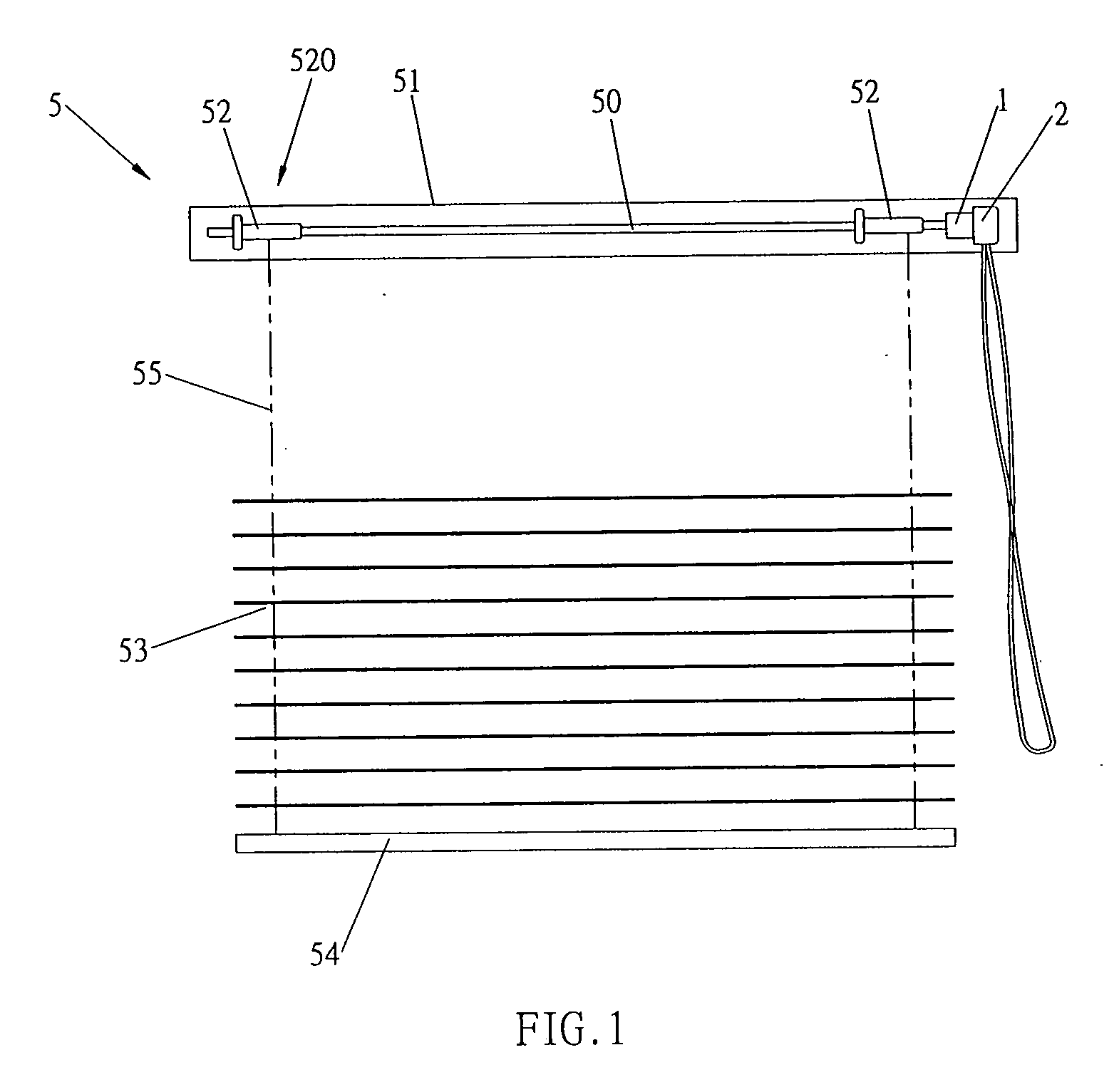
[0038] The drive unit 2 synchronously rotates a circular box 32 of the brake mechanism 3 through a sprocket wheel 21, which is actuated by means of a beaded chain 210.

[0039] A section between the sprocket wheel 21 and the box 32 functions as an independent component, and a connected body of such is assembled by means of a socket joint or a single body can be formed by ejaculation.

[0040] A through hole 320 is frontward configured in the circular box 32, and an interior of the box 32 is adapted so as to form a circular slot 321, which provides for a shield-shaped rotor 31 to be disposed therein. An insertion hole 311 is defined center of the shield-shaped rotor 31, which p...


PUM


Abstract

A brake mechanism for curtain linkage system, which provides an improved mechanism for application in a curtain set such that when curtain slats are subjected to external forces that produce a counterforce, the counterforce is utilized to achieve a reverse braking effect. The brake mechanism can outwardly transmit motive power inputted to a drive unit to a connected linkage shaft. More specifically, the brake mechanism comprises a shield-shaped rotor disposed interior of a circular box. A confining ring is configured on a periphery of the circular box, and a rolling pin is configured between an inner circumference of the confining ring and a rotor, and the rolling pin functions to effectuate a shearing effect. Relative motion of the rolling pin and the rotor realizes a reverse braking effect in the confining ring, and which successfully achieves functionality of the brake mechanism of the present invention.

Description

BACKGROUND OF THE INVENTION [0001] (a) Field of the Invention [0002] The present invention relates to a brake mechanism for curtain linkage system, and more particularly to an improved mechanism for application in a curtain set such that when curtain slats are subjected to external forces that are transmitted back to a transmission mechanism, the forces are utilized to realize a braking effect. The brake mechanism of the present invention primarily comprises a shield-shaped rotor, and after inter-configuring a rolling pin, am immobile periphery confining ring functions as basis to effectuate the braking effect. [0003] The rotor is disposedly contained in a circular box, and the rolling pin is subjected to synchronous rotation about a same angular position along with rotational displacement of the circular box. [0004] (b) Description of the Prior Art [0005] Regarding necessity for configuring a brake mechanism in a curtain linkage system, during course of actuating release of curtain...

Claims


Application Information

Patent Timeline
IPC IPC(8): E06B9/30
CPCE06B2009/3227E06B9/32
Inventor HUANG, SHIEN-TE
Owner HUANG SHIEN TE
Why Eureka
Try Eureka