Precision tactical mount

Inactive Publication Date: 2010-06-08
BLACK ROBERT O
View PDF25 Cites 57 Cited by
  • Summary
  • Abstract
  • Description
  • Claims
  • Application Information

AI Technical Summary

Benefits of technology

[0003]A novel precision tactical mount is disclosed having a vertical controller for determining elevation direction and a horizontal controller for determining azimuth direction. The vertical controller and the horizontal controller have friction means for selectively determining specific resistance to angular movement of a rigid support member about respective axes. The horizontal controller provides adjustment of specific resistance to moving about a vertical axis for aiming the tactical mount in selected horizontal directions. A vertical controller provides adjustments for both specific resistance to moving about a horizontal axis and a threaded fine control adjustment mechanism for determining the elevation at which the object is aimed. The specific resistance adjustments for both the horizontal controller and the vertical controllers allow users to continuously track a moving target with a smooth and continuous motion, at the same time as fine tuning adjustments may be made to specifically determine actual resistance against angular movement of the precision tactical mount without interfering with smooth angular motion of the tactical mount and wit

Problems solved by technology

Release and then securing of coarse adjustment mechanisms typically results in a bumping movement, in which the direction in which the object is aimed jumps to a direction which is not directly pointing toward the target, requiring re-acquisition of the target after course adjustments are made.
Follow

Method used


Image

  • Precision tactical mount
  • Precision tactical mount
  • Precision tactical mount

Examples


Embodiment Construction

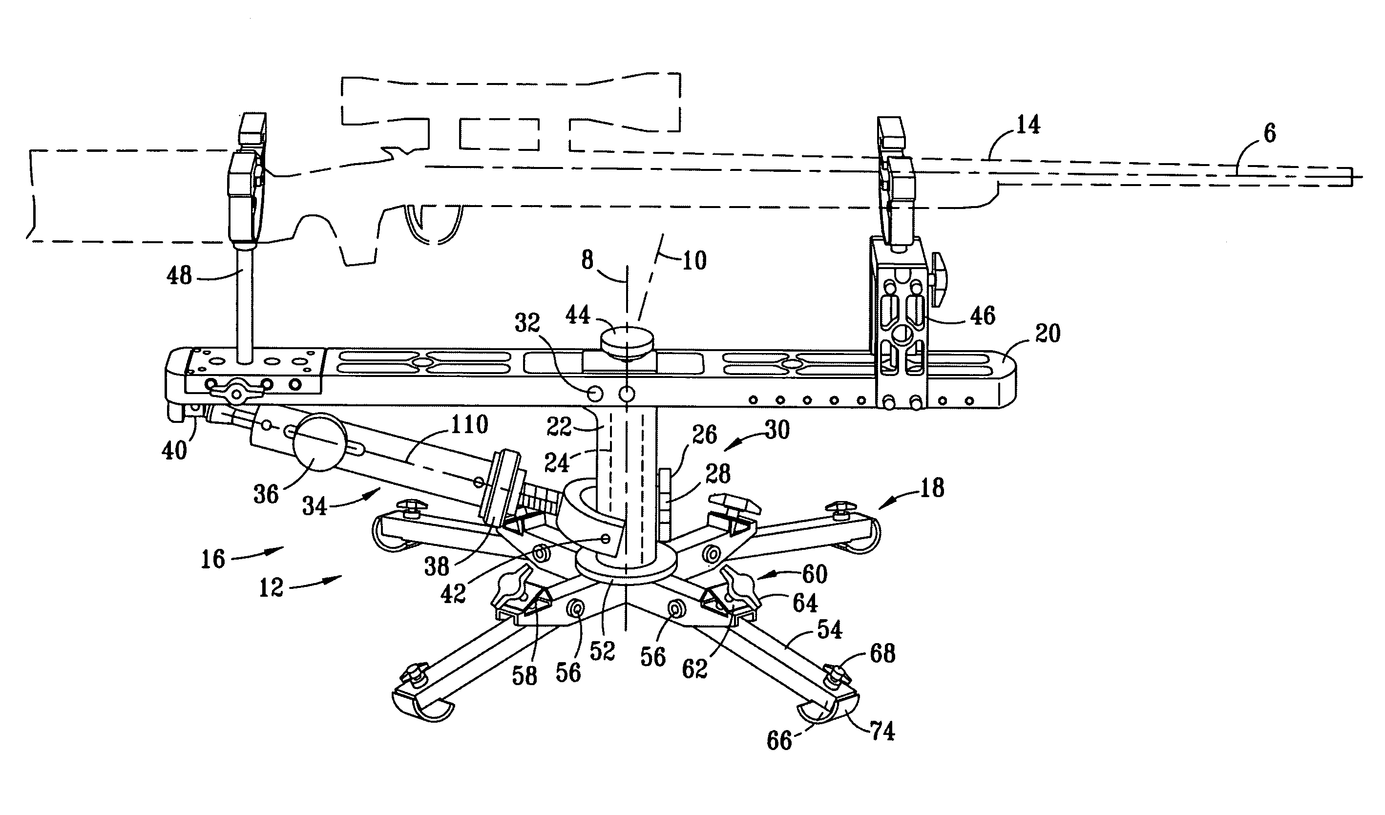
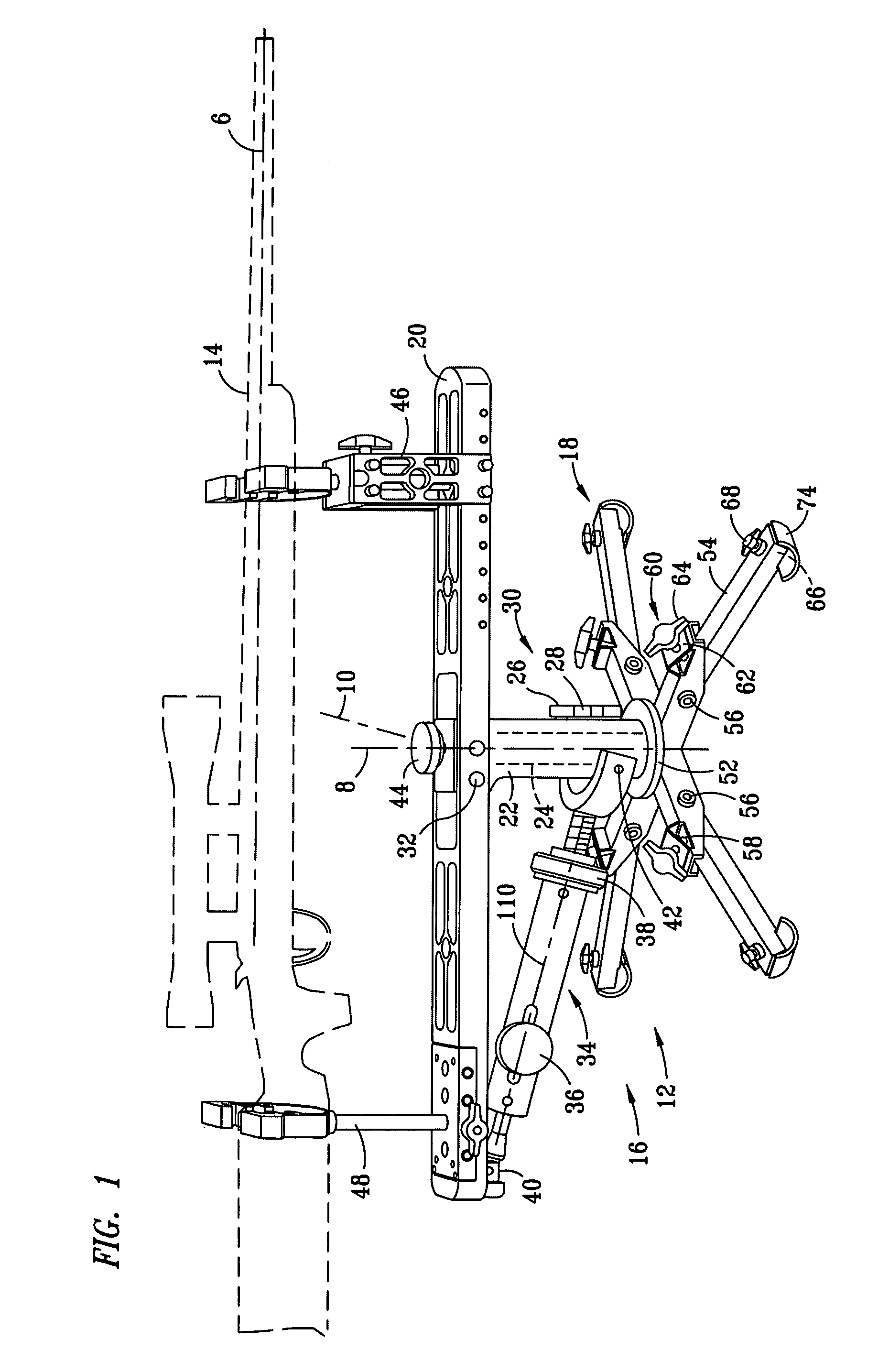
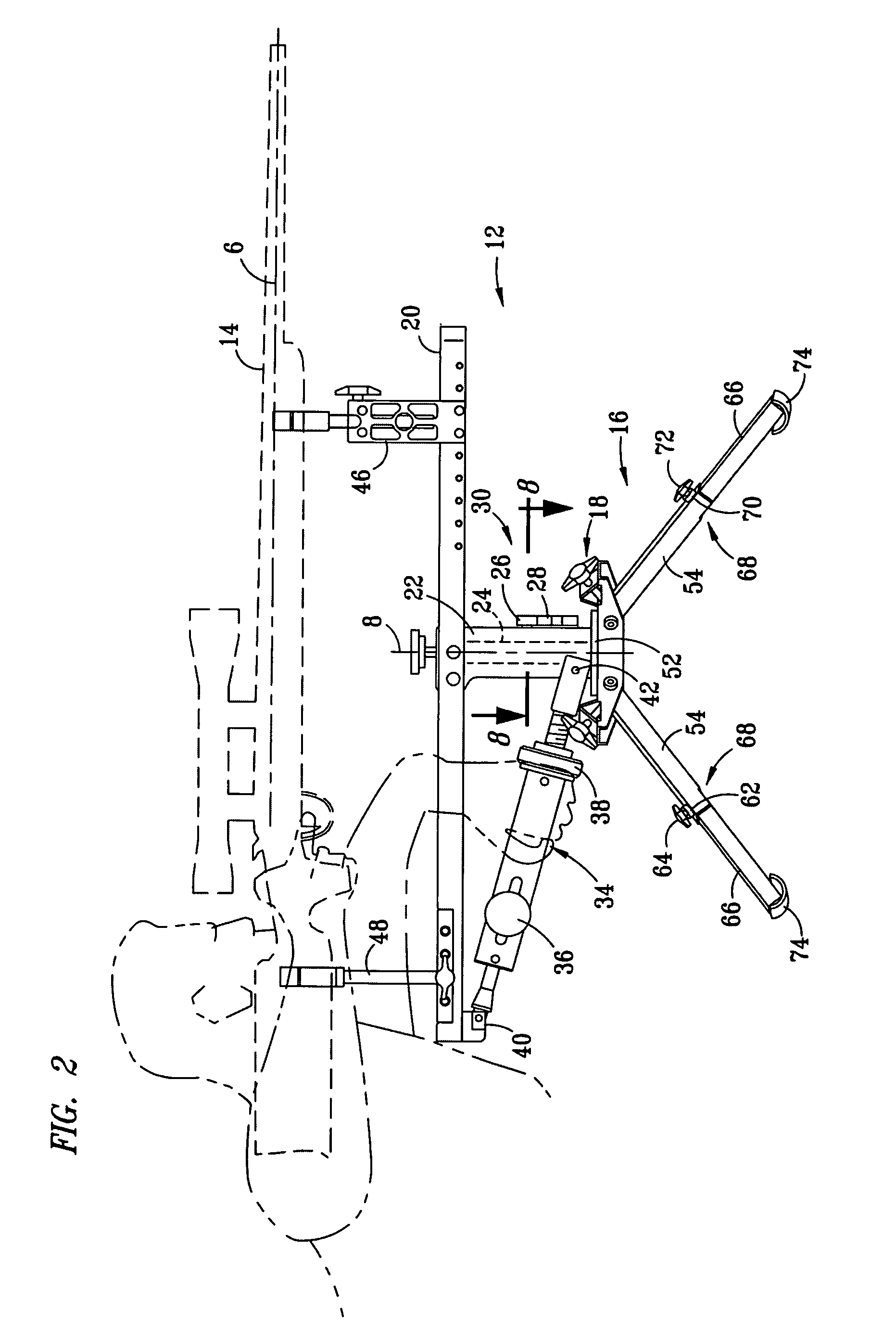
[0013]FIG. 1 is a perspective view and FIG. 2 is a side elevation view of a precision tactical mount 12 for mounting a firearm 14 and selectively moving a centerline 6 of a barrel for the firearm 14 around an axis 8 for an azimuth angle and an axis 10 for an elevation angle in aiming the firearm 14 at a target. The precision tactical mount 12 includes a mounting assembly 16 and a mounting base 18. The mounting assembly 16 includes a rigid mounting member 20 which is pivotally mounted to the mounting base 18 by support member 22. The support member 22 is rotatably secured to a spindle 24. The spindle 24 is preferably welded to a mounting plate 52 which is secured to the mounting base 18.

[0014]The mounting assembly 16 includes a selectively adjustable friction lock 26 which provides a rotary lock 28 and a horizontal controller 30 for determining an angular direction in which the mounting member 20 extends. The selectively adjustable friction lock, or rotary lock, 26 provides a specifi...


PUM


Abstract

A precision tactical mount (12) includes a horizontal controller (30) and a vertical controller (34) for determining azimuth angles and elevation angles for a sight line of the precision tactical mount (12). The horizontal controller (30) and the vertical controller (34) have friction blocks (102, 114, 196) which engage mating friction surfaces with selectable forces for providing specific resistance against azimuth and elevation angular movement, without requiring separate mechanisms for locking the tactical mount (12) in selected positions. The friction blocks (102, 114 and 196) are preferably formed of softer materials than the mating friction surfaces to conform to the shape of the mating friction surfaces with increased normal forces, providing varying surface areas. The vertical controller (34) includes a course threaded screw member (142) mounted at an angle to a centerline (6) of the precision tactical mount (12) to provide fine control adjustment for elevation.

Description

TECHNICAL FIELD OF THE INVENTION[0001]The present invention relates in general to tactical mounts, and in particular, to a tactical mount for selectively aiming an object at a target.BACKGROUND OF THE INVENTION[0002]Prior art tactical mounts have been provided for aiming various objects at targets. Objects being aimed have included firearms, such as hunting rifles and tactical weapons, cameras, and the like. Prior art tactical mounts for controlling the aim of an object at targets have included fine and course threaded adjustments for aiming the objects relative to two different axes, such for determining an azimuth angle and elevation for a sight line of the object. Some prior art tactical mounts have included two sets of fine and course threaded adjustment mechanisms, each set corresponding to different perpendicular axes for azimuth and elevation. Typically, fine adjustment mechanisms are provided by micro-screw threaded assemblies having very fine screw threads. Course adjustmen...

Claims


Application Information

Patent Timeline
IPC IPC(8): F41A23/00
CPCF41A23/16F41A23/02
Inventor BLACK, ROBERT O.
Owner BLACK ROBERT O
Why Eureka
Try Eureka