Solenoid with path converter

a technology of path converter and solenoid, which is applied in the field of solenoid, can solve problems such as development and design, and achieve the effect of large stroke and high flexibility

Inactive Publication Date: 2010-06-08
WOLFGANG E SCHULTZ
View PDF13 Cites 59 Cited by
  • Summary
  • Abstract
  • Description
  • Claims
  • Application Information

AI Technical Summary

Benefits of technology

[0008]This solution according to the invention leads to surprising results. By means of this suggestion according to the invention it is also achieved, however, that now the solenoid can be optimised for different requirements, and that is even if this optimising processes at the solenoid have the result that the armature carries out a larger stroke. By means of the equipment according to the invention with the path converter this increased stroke can be compensated again, and an optimising of the solenoid altogether is achieved, for example with respect to its power performance (respectively its characteristic) and the stroke of the armature bar. It may be possible to optimise contrasting characteristics of the solenoid together and to achieve a clearly improved apparatus. A solenoid with such an equipment has therefore a high flexibility, and can be applied in a number of applications.
[0009]The solenoid according to the invention has here a path converter which, at first, does not carry out a power transformation. Besides the losses of friction, the path converter changes only the stroke. Alternatively to that, of course, also arrangements are possible where the path converter is designed like a gear or a lever arrangement, and it carries out a power transformation to about that degree to which also a reciprocal path conversion with respect to the conservation of energy is carried out. Such a design makes the arrangement according to the invention even more flexible as it is not directly limited to the power spectrum provided by the solenoid, but it becomes more flexible even here.
[0016]In a development of the solution according to the invention it is suggested that the armature bar is guided by the spring or springs over a cylindrical, respectively pocket-like, receptacle. In contrast to the solutions known from the state of the art the armature bar is not guided loosely in a recess, but a housing designed pot-like or tube-like holds one or more springs as well as a receptacle. The springs are supported, on the one hand, by the bottom of the housing, and, on the other hand, by a flange of the receptacle. The armature bar is in this receptacle, and that means even in contact with the bottom. Thus the armature bar is guided, according to the present modification of the invention, by springs over a cylindrical or pocket-like receptacle, and is not located loosely in a recess. The receptacle here is not an operating part, either, as it is necessary with the solutions known from of the state of the art. The modification described before is therefore more convenient because it is less expensive.

Problems solved by technology

If a relatively small stroke is required for that possibly a separate solenoid with a small stroke has to be developed and designed, which is expensive.

Method used


Image

  • Solenoid with path converter
  • Solenoid with path converter
  • Solenoid with path converter

Examples


Embodiment Construction

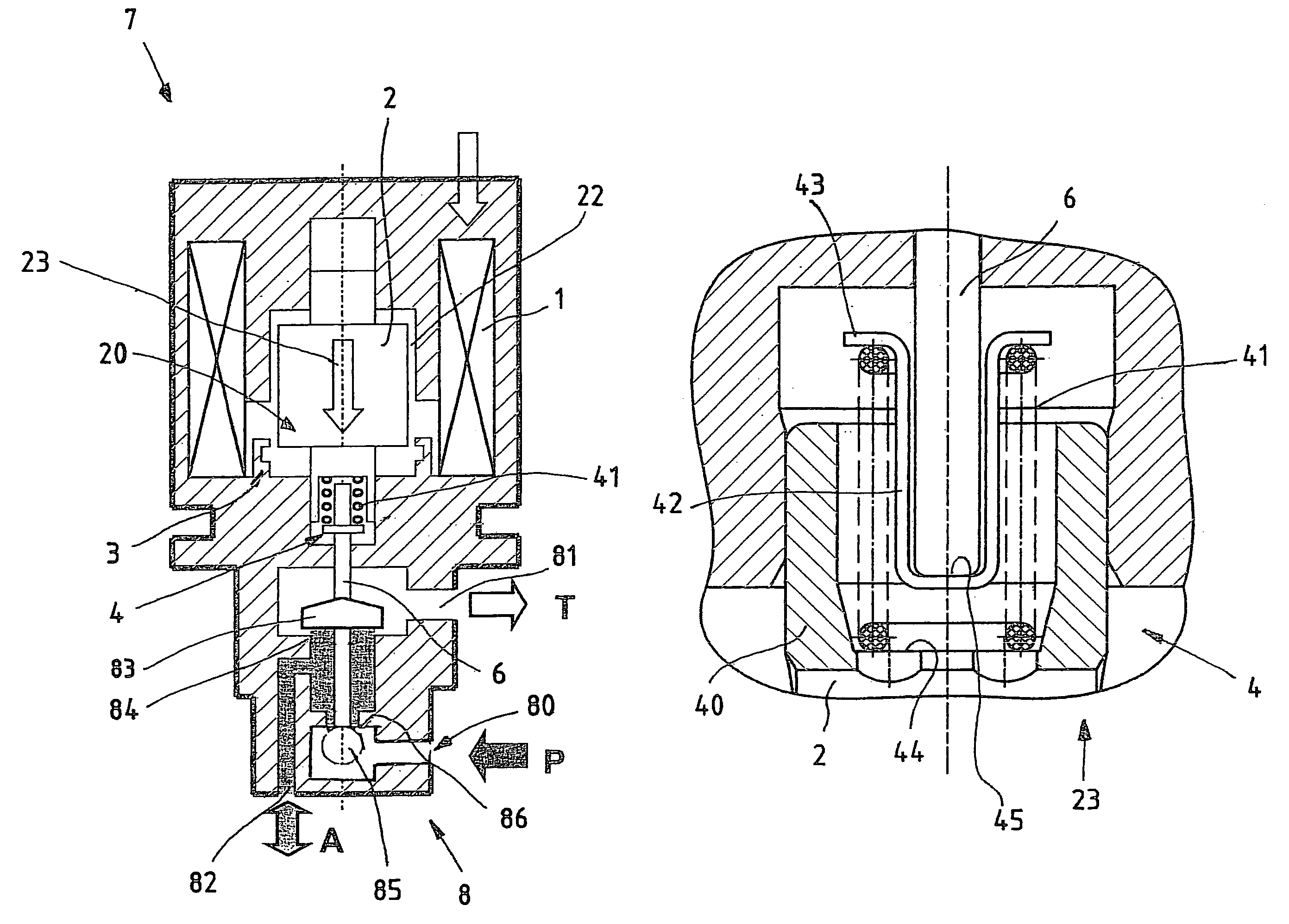
[0035]The solenoid 7 according to the invention can in particular be seen in FIG. 1. The solenoid 7 comprises an armature 2 movable in an armature room 22. The armature room 22 is surrounded by the coil 1. The coil 1 generates a magnetic field, when flowed through by current, which effects that the armature 2 is moved downward (arrow 23).

[0036]In the view shown in FIG. 1 there is the control cone 3 in the bottom region of the armature room 22. When flowed through by current, the armature 2 moves in the control cone 3, the particular design of the control cone 3 leading to a progressive run of the characteristic.

[0037]The example shown in FIG. 1 shows a valve 8 driven by the solenoid 7 which is called, for example, pressure control valve. For that the armature 2 acts on an armature bar 6 which is joined below the armature 2 outside the armature room 22.

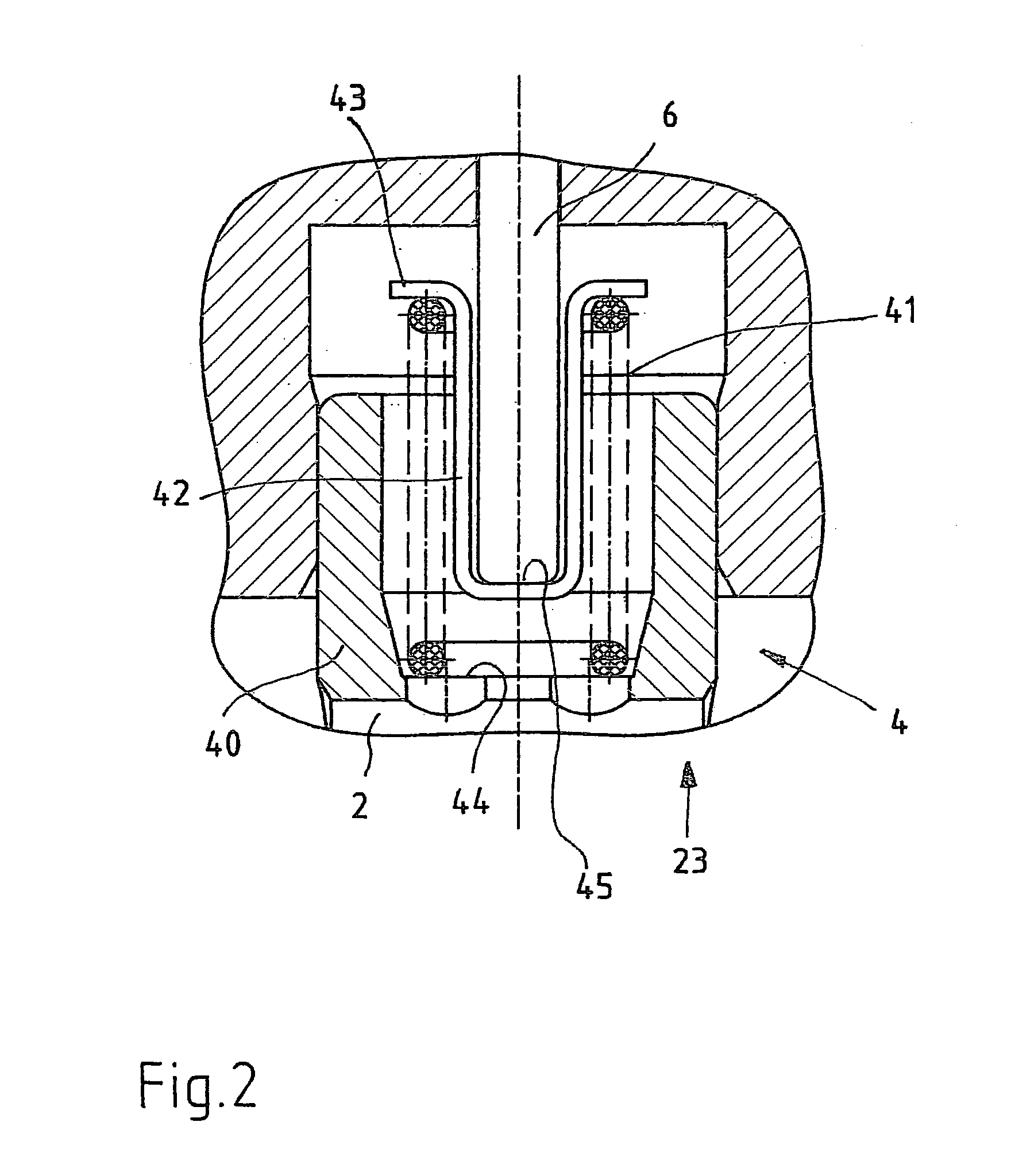
[0038]In the example shown here a path converter 4 is arranged between the armature 2 and the armature bar 6. The path converter 4 ef...


PUM


Abstract

A solenoid including an armature movable in an armature room and a coil which can be flowed through by current. When it is flowed through by current the armature moves. The armature interacts with an armature bar. A path converter is provided between the armature and the armature bar.

Description

BACKGROUND OF THE INVENTION[0001]The invention refers to a solenoid comprising an armature movable in an armature room, and a coil which can be flowed through with current, wherein the coil generates, when flowed through with current, a magnetic field which serves for moving the armature, and the armature acts on an armature bar.[0002]The solenoids described in the beginning are sufficiently known. They serve, for example, as control or circuit elements wherein by means of the solenoid a corresponding control or circuit part is moved. This movement is transmitted by the armature to an armature bar, the armature bar then influencing or operating the control, respectively the circuit member. For the connection between armature and armature bar it is known either to couple them rigidly or to connect them loosely.[0003]In the state of the art also a solenoid valve is known which serves for adjustment of a pressure and / or a flow of a hydraulic fluid. This solenoid valve with axle absorpt...

Claims


Application Information

Patent Timeline
Patent Type & Authority Patents(United States)
IPC IPC(8): F16K31/04
CPCH01F7/1607H01F7/088Y10T137/86622Y10T137/86678
Inventor KLEINERT, DIETERSCHERER, GEORGMANG, HELMUT
Owner WOLFGANG E SCHULTZ
Why Eureka
Try Eureka