
Apparatus support structure

a support structure and apparatus technology, applied in the field of apparatus support structure, can solve the problems of difficult cleaning of bodies and unsatisfactory, and achieve the effect of high degree of freedom

Active Publication Date: 2010-06-08
KRONES AG
View PDF7 Cites 14 Cited by
  • Summary
  • Abstract
  • Description
  • Claims
  • Application Information

AI Technical Summary

Benefits of technology

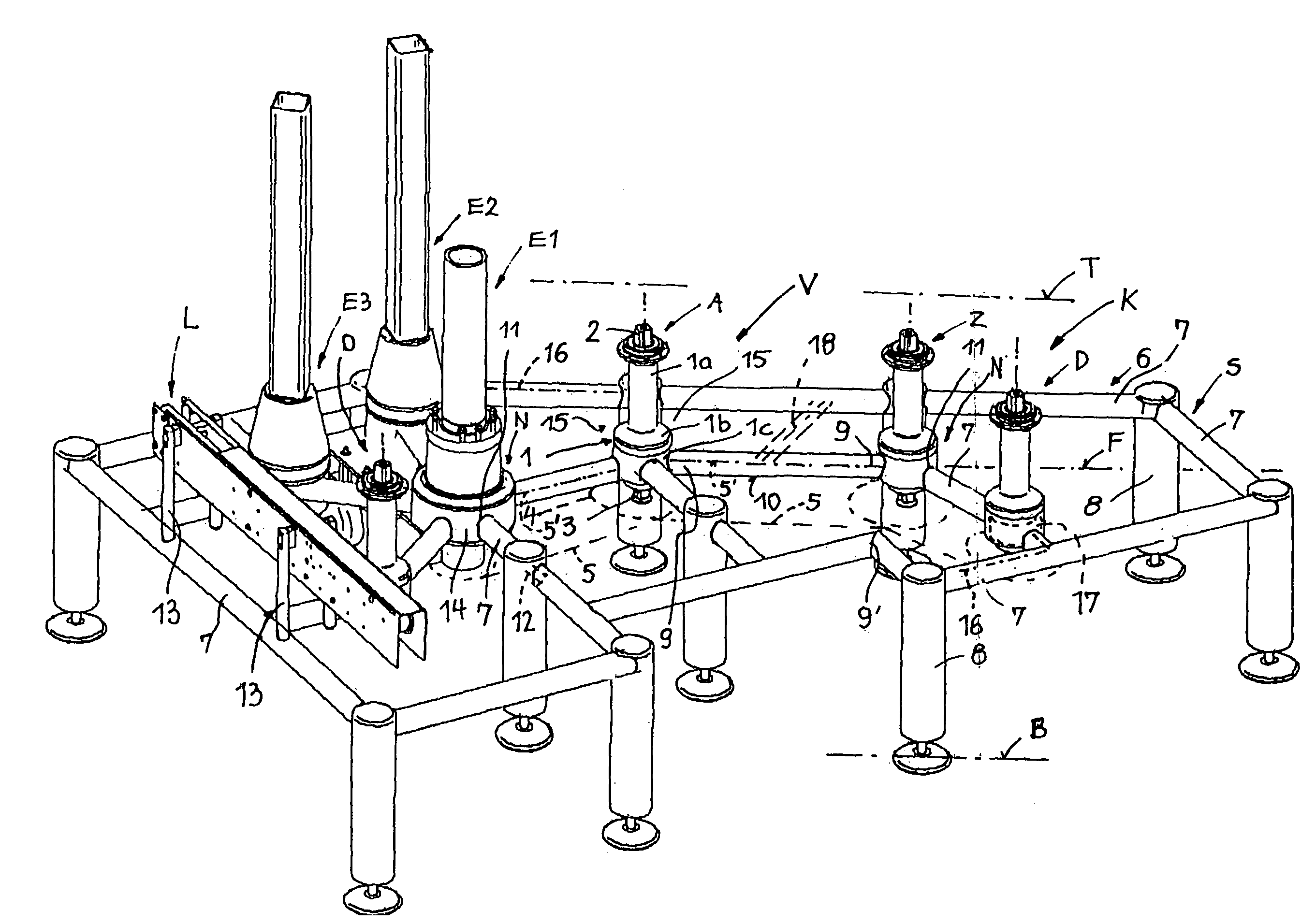
[0007]In contrast to the known principle of the large-surface plate body and the duct carrier support structure in the form of an arc of a circle, a pipe or profile frame with feet, which is composed of sections, is used as support structure. The sections serve not only for the formation of the frame, but also for positioning, and they carry at nodes support housings for stars, such as, for example, entry and exit stars, or similar parts. The apparatus support structure is advantageous with regard to cleaning, for example, because only small surfaces that slant downward are provided on the sections, on which fluids can immediately run off, and also because large free spaces are created around the support housing. The support housing and the sections can be combined as desired, and they make it possible to adapt or modify the apparatus support structure and the given star configuration in a modular construction to the individual application cases, for example, by the addition or removal of star and / or container handling components. The sections of the pipe or profile frame and the support housing form a kind of modular set, from which different star configurations can be prepared. Because the free spaces are clear from the fixation level to the floor, it is possible to integrate in this area without any problem an open drive system, at least for the stars. Individual components, for example stars, can be exchanged at any time without having to attach the entire composite structure.
[0018]In an alternative embodiment, beneath the fixation plane on the bottom sides of the support housing, drive wheels, such as sprocket wheels, toothed wheels or belt toothed wheels, are arranged free-standing and connected by uncovered drive connections (meshing toothed wheels, chains, toothed belts or articulation shafts) to a central drive system. This open drive system can be designed so it is safe from the hygienic point of view and can be cleaned without problems.

Problems solved by technology

Such conventional apparatus support plate bodies are difficult to clean and unsatisfactory from a microbiological point of view.

Method used


Image

  • Apparatus support structure
  • Apparatus support structure

Examples


Embodiment Construction

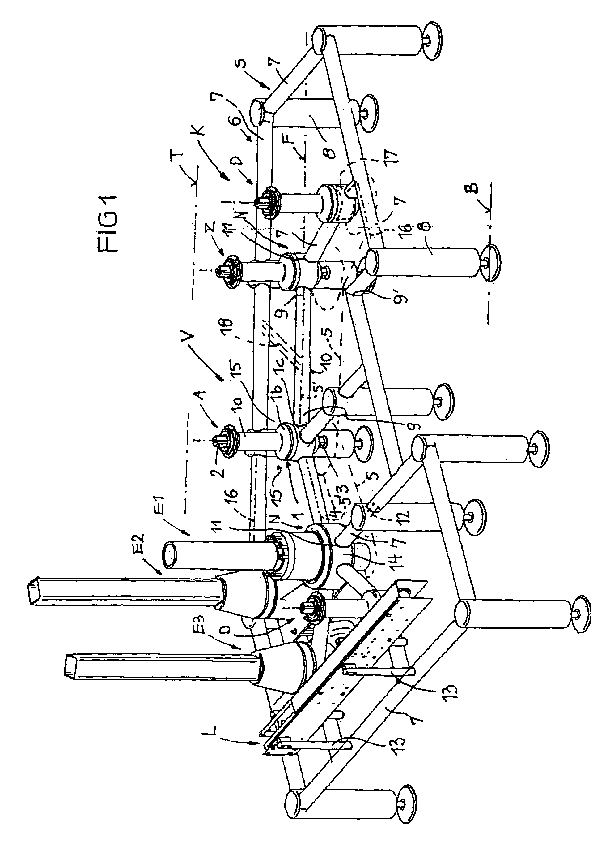
[0024]Schematically represented apparatus support structure V in FIG. 1 is associated operatively with a container handling machine—not shown—, for example a bottle filling machine, in such a manner that transport routes of the apparatus support structure V, which run in a transport plane T, are connected to the transport routes in the container handling machine. The transport of the containers into and out of the container handling machine is carried out primarily by means of the apparatus support structure V, where, however, additional container handling components can be incorporated in the apparatus support structure, optionally at the entry side or the exit side. In the embodiment shown in FIG. 1, an entry and exit apparatus support structure V is completed, for example, by the closing devices E1, E2, E3 and an additional conveyor L, as well as at least one transfer star D.

[0025]A support structure S of the apparatus support structure V is formed by a pipe or profile frame 6, w...


PUM


Abstract

The invention relates to a pre-table system (V) for container handling machines, comprising at least in-feed and out-feed starwheels (A, Z), arranged such as to be driven on support housings (1), defining a starwheel configuration (K) in the pre-table system (V), within which the support housing (1) is fixed to a floor-standing support structure (S) whereby the support structure (S) has a tube and / or profile section frame (6) of sections (7) directly or indirectly detachably connected to each other at points (N) by means of the support housing and floor support feet (8), within which the support housings are arranged in a free-standing manner such that free areas (15) are formed around the support housings and at least some sections (7) may be combined together and with support housings such that the starwheel configurations (K) may be optionally altered.

Description

CROSS-REFERENCE TO RELATED APPLICATION[0001]This is the U.S. national stage under 35 U.S.C. §371, of international application no. PCT / EP2006 / 000974, having an international filing date of Feb. 4, 2006, and claims priority to German application no. 20 2005 002 469.4 filed on Feb. 16, 2005.FIELD OF THE DISCLOSURE[0002]The disclosure relates to an apparatus support structure according to the preamble of claim 1.BACKGROUND OF THE DISCLOSURE[0003]The usual standard for apparatus support structures for container handling machines, such as bottle filling machines, is a plate body, in which at least the entry and exit stars, optionally also transfer stars, and optionally other container handling components are mounted in predetermined positions. Such conventional apparatus support plate bodies are difficult to clean and unsatisfactory from a microbiological point of view. Moreover, the given star configuration is rigidly established and not variable.[0004]From EP 1 316 520 A, an apparatus ...

Claims


Application Information

Patent Timeline
Patent Type & Authority Patents(United States)
IPC IPC(8): B65G21/00B65G37/00B65G41/00B65G47/00B65B59/00B65G47/84B67C3/22F16M5/00
CPCB65G47/846F16M5/00B67C3/22
Inventor ZEPF, GEORG
Owner KRONES AG
Learn More