
Medication fluid tube stabilization device

a technology of fluid tube and medication, which is applied in the direction of mechanical equipment, other domestic objects, machine supports, etc., can solve the problems of increasing the risk of patients, increasing the pain of patients, and delivering appropriate amounts of fluids in hospital beds, so as to reduce the pain of patients and relieve the stress.

Inactive Publication Date: 2010-06-08
FRICKERRAINESSINNOTT
View PDF15 Cites 5 Cited by
  • Summary
  • Abstract
  • Description
  • Claims
  • Application Information

AI Technical Summary

Benefits of technology

"The invention is a device that reduces pain associated with intravenous fluid delivery. It consists of a resilient tube-like device with two overlapping sides that hold the device on a bed rail. The device also has flaps that can hold fluid tubes and allow them to move freely in directions that are generally transverse to the direction of the slit and the bed rail. The flaps also provide a surface for writing fluid information. The invention is reliable, affordable, and can help alleviate pain associated with intravenous fluid delivery."

Problems solved by technology

Delivering appropriate amounts of fluids intravenously to a patient in a hospital bed is often painful and even can be dangerous for the patient depending on the circumstances.
Whenever the patient moves to change position, however, the length and weight of the tubes drag against their attached needles causing considerable pain for the patient.
Occasionally, the patient's movement can be extremely painful if one or more of the needles under the weight of the tube tear out of the patient's body.
A further problem can arise from the incorrect identification of a particular tube with its associated fluid source.
For example, in situations in which a patient is receiving several intravenous fluids at the same time, the jumble of tubes joining respective intravenous fluid sources to their associated needles can be very confusing, especially to a nurse or nurse's aid working under great pressure and responsible for the care of a number of patients.
Controlling the rising cost of medical care and the expensive apparatus that this care requires is a widely known problem.

Method used


Image

  • Medication fluid tube stabilization device
  • Medication fluid tube stabilization device
  • Medication fluid tube stabilization device

Examples


Embodiment Construction

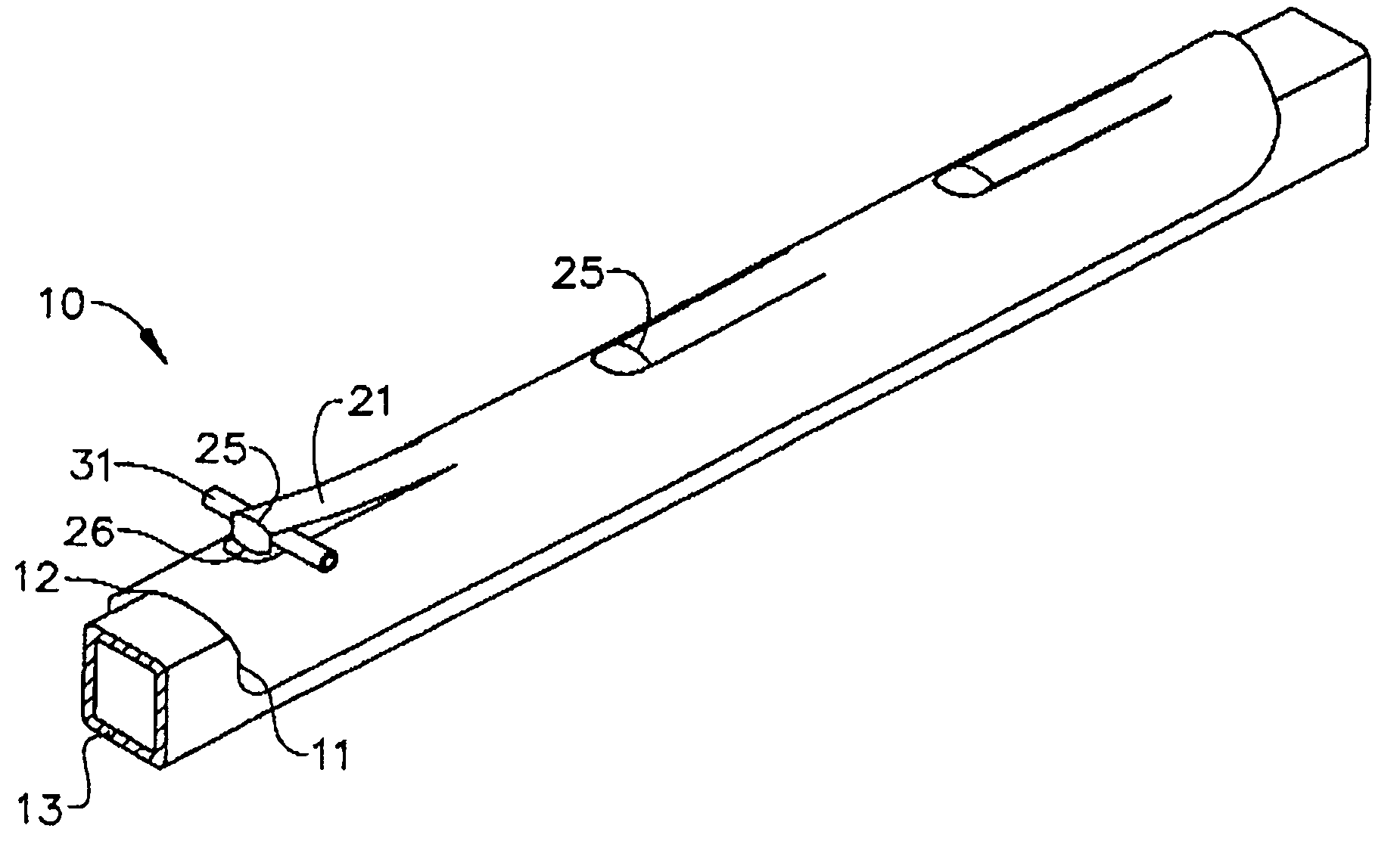
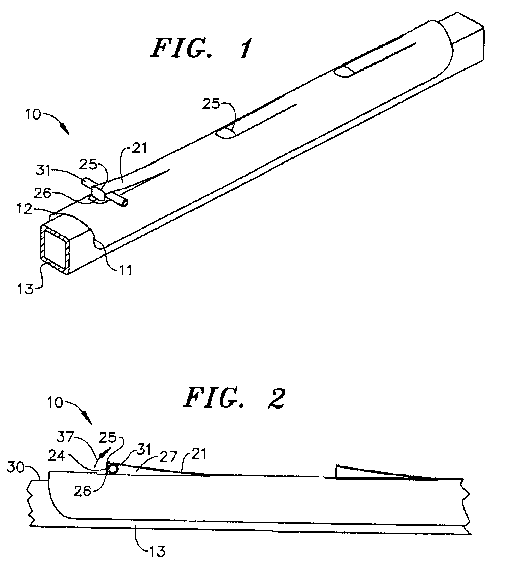
[0021]For a more complete appreciation of the invention, attention is invited to FIG. 1 which shows a generally cylindrical member or fluid tube stabilization device 10 in which sides 11, 12 clamp the device 10 to top bed rail 13.

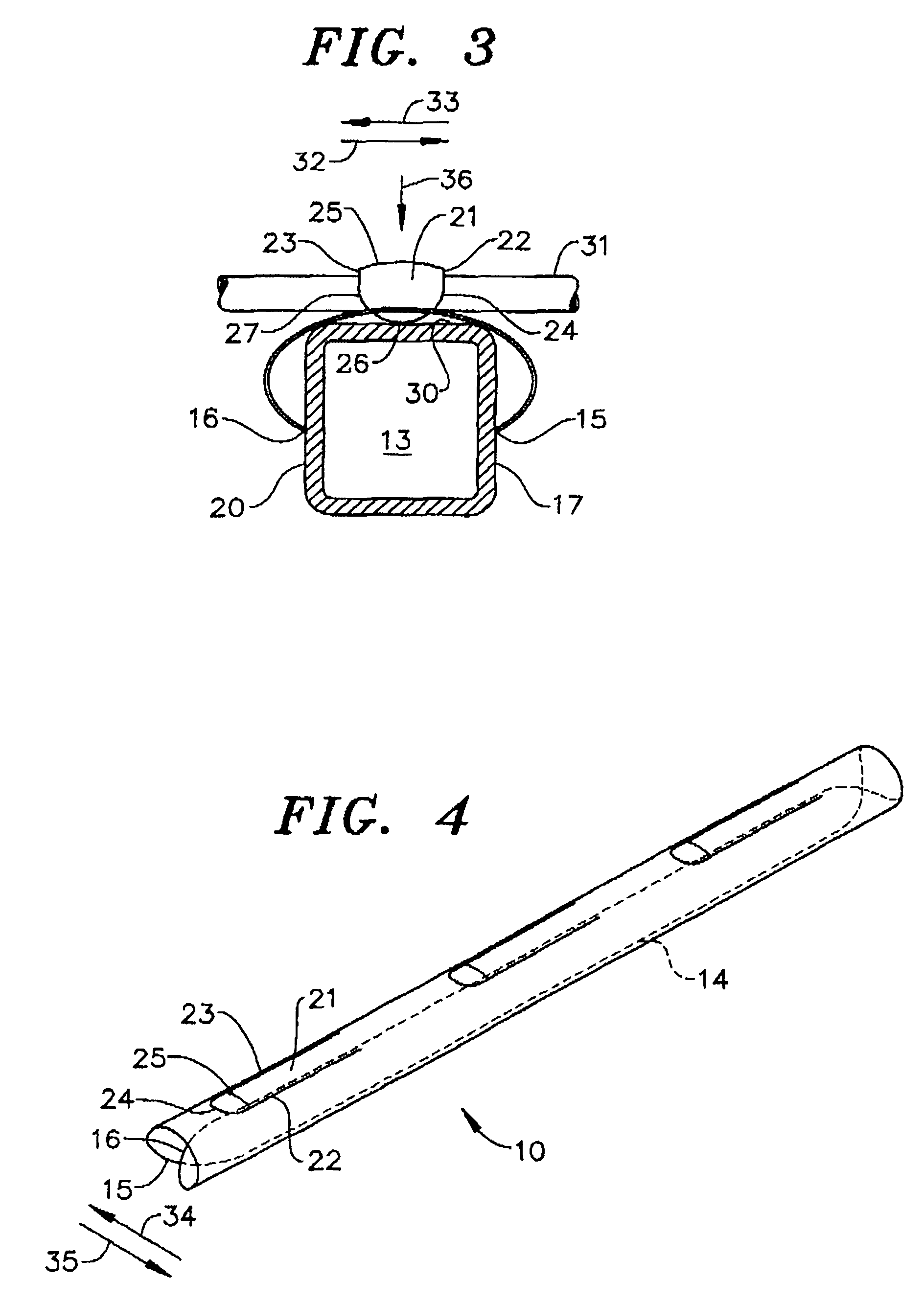
[0022]Preferably, the device 10 is formed from a resilient clear plastic tube that enjoys a suitable degree of elasticity. Thus, device 10 shown in FIG. 4 in a relaxed or unstressed state has been provided with a lengthwise slit 14 that forms two overlapping surfaces 15, 16. As described subsequently, the surfaces 15, 16 can be manually spread apart and pressed over the bed rail 13 as shown in FIG. 3 to bear against and engage corresponding portions 17, 20 of the top bed rail 13. As shown, the inherent resiliency of the device applies sufficient frictional force through the now separated surfaces 15, 16 to the corresponding portions 17, 20 of the bed rail 13 to clamp or retain the device 10 firmly in engagement with the bed rail 13 through the stresses that...


PUM


Abstract

An interactive fluid tube stabilization device for an intravenous feeding tube is formed of an acrylic material that has a cylindrical shape. A lengthwise slit forms two overlapping sides for the device that can be manually spread apart to fit over and clamp onto the top bed rail of a hospital bed. A flap formed in the side of the device that is opposite to the slit has an arcuate end and a fold line spaced from the end through a distance that is greater than the diameter of the intravenous feeding tube. When the arcuate end is bent toward the top of the bed rail, it forms a gap that accommodates the feeding tube between the device and the flap, enabling most of the drag applied by the feeding tube to be borne by the device and to permit relatively free movement of the tube transverse to the bed rail to accommodate the movement of the patient.

Description

CROSS-REFERENCES TO RELATED APPLICATIONS[0001]NoneSTATEMENT REGARDING FEDERALLY SPONSORED RESEARCH OF DEVELOPMENT[0002]NoneNAMES TO THE PARTIES TO A JOINT RESEARCH AGREEMENT[0003]NoneREFERENCE TO “SEQUENCE LISTING”[0004]NoneBACKGROUND OF THE INVENTION[0005]This invention relates to devices for stabilizing medication fluid tubes and, more particularly, to an apparatus for supporting a medication fluid tube on a top bed rail in a manner that sustains most of the tube weight and enables the tube to move freely and transversely relative to the bed rail in response to the movement of a patient receiving intravenous medication from the tube, and the like.[0006]Delivering appropriate amounts of fluids intravenously to a patient in a hospital bed is often painful and even can be dangerous for the patient depending on the circumstances. For example, a patient in a hospital bed frequently receives fluids and medications intravenously. This delivery method requires a needle introduced through ...

Claims


Application Information

Patent Timeline
Patent Type & Authority Patents(United States)
IPC IPC(8): F16L3/22
CPCA61G7/0503A61M5/1418A61G2007/0524A61G7/0524Y10S128/06Y10S128/26
Inventor RAINES, JR., LARRY
Owner FRICKERRAINESSINNOTT
Learn More