Integrated control of brake and steer by wire system using optimal control allocation methods

a wire system and optimal control technology, applied in the direction of steering of non-deflectable wheels, braking components, underwater vessels, etc., can solve the problems of less vehicle deceleration and asymmetric brake force distribution, and achieve the effect of facilitating numerical solutions to the control allocation problem

Inactive Publication Date: 2010-06-08
THE UNITED STATES OF AMERICA AS REPRESETNED BY THE SEC OF THE AIR FORCE
View PDF9 Cites 37 Cited by
  • Summary
  • Abstract
  • Description
  • Claims
  • Application Information

AI Technical Summary

Benefits of technology

[0007]The present invention addresses these and other problems of the prior art by providing an apparatus and method of optimizing drive-by-wire vehicles as a control allocation problem, in which an optimal solution can quickly be determined in real time using linear programming techniques. The apparatus and method comprise: (1) determining the desired motion of vehicle in the yaw plane using driver steering and brake inputs; (2) accessing a stored model that correctly describes the vehicle dynamics in the yaw plane in all operating conditions and poses a structure, which facilitates the numerical solution to the control allocation problem; and (3) numerically solving the optimal control allocation problem quickly, with reference to control input, to minimize the difference between the desired and actual vehicle motion under all constraints placed on actuators.

Problems solved by technology

This has two undesirable effects on vehicle dynamics: 1) vehicle deceleration is less than desired since the total braking force acting on the vehicle is reduced; and 2) brake force distribution becomes asymmetric, pulling the vehicle to the side as a result of unbalanced yaw moment acting on the vehicle.

Method used


Image

  • Integrated control of brake and steer by wire system using optimal control allocation methods
  • Integrated control of brake and steer by wire system using optimal control allocation methods
  • Integrated control of brake and steer by wire system using optimal control allocation methods

Examples


Embodiment Construction

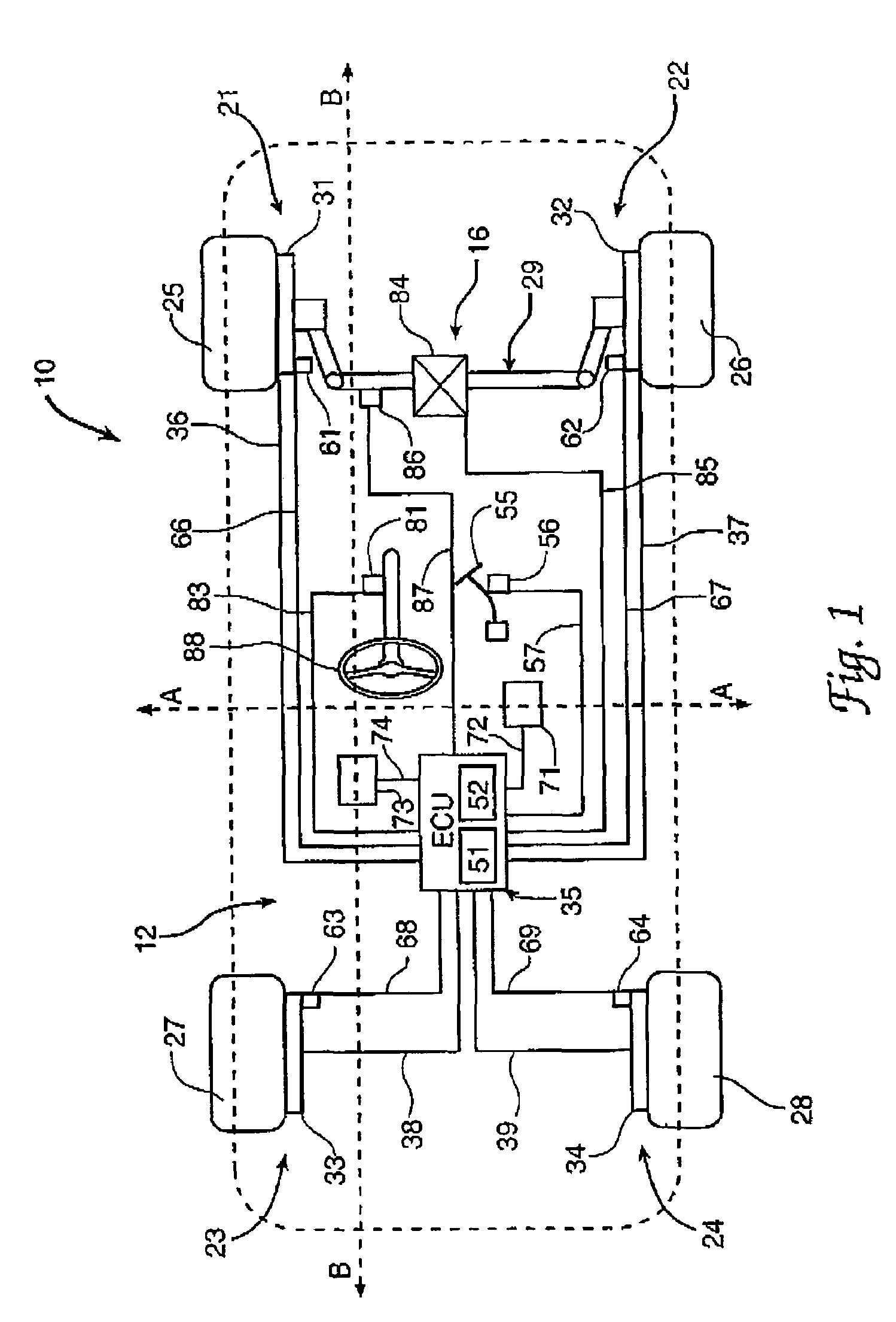
[0015]Referring to the drawings, wherein like reference numerals refer to like elements, FIG. 1 is a schematic view of a vehicle, shown generally by numeral 10, with a vehicle brake system 12 in accordance with the present invention. Those skilled in the art will recognize that the vehicle 10 and vehicle brake system 12 may include a number of alternative designs and may be employed in a variety of applications. For example, as will be described, the vehicle 10 may include various sensor(s), active brake-by-wire (BBW) and steer-by-wire (SBW) systems as part of different embodiments of the vehicle brake system 12.

[0016]In the present description and figures, the vehicle 10 and the vehicle brake system 12 include both a BBW system 14 and a SBW system 16 for selectively inhibiting wheel rotation during brake failure while limiting an undesired yaw moment to an acceptable level. In portions of the following description, the SBW system 16 may be omitted to provide a vehicle including onl...


PUM


Abstract

A method, computer usable medium including a program, and a system for braking a vehicle during brake failure. The method and computer usable medium include the steps of determining a brake force lost corresponding to a failed brake, and determining a brake force reserve corresponding to at least one non-failed brake. At least one commanded brake force is determined based on the brake force lost and the brake force reserve. Then at least one command brake force is applied to the at least one non-failed brake wherein at least one of an undesired yaw moment and a yaw moment rate of change are limited to predetermined values. The system includes a plurality of brake assemblies wherein a commanded brake force is applied to at least one non-failed brake.

Description

RIGHTS OF THE GOVERNMENT[0001]The invention described herein may be manufactured and used by or for the Government of the United States for all governmental purposes without the payment of any royalty.FIELD OF THE INVENTION [0002]The present invention relates generally to steering and brake systems. More particularly, the invention relates to strategies for braking a vehicle during brake failure.BACKGROUND OF THE INVENTION [0003]This document describes a new control strategy for dealing with failure of brake actuators in vehicles equipped with brake-by-wire systems and possibly with steer-by-wire systems. Brake-by-wire systems refer to any brake system in which brake actuators at each wheel can be controlled independently of the driver input and of each other. Steer-by-wire systems are steering systems in which the front (or rear) steering angle can be controlled independently of the driver, providing means of imparting a steer angle correction when necessary.[0004]Algorithms for fa...

Claims


Application Information

Patent Timeline
Patent Type & Authority Patents(United States)
IPC IPC(8): G06F19/00
CPCB60T8/885B62D6/003B60W50/029B60T2260/02B60T2270/402B60T2260/08
Inventor OPPENHEIMER, MICHAEL W.DOMAN, DAVID B.HAC, ALEKSANDER B.
Owner THE UNITED STATES OF AMERICA AS REPRESETNED BY THE SEC OF THE AIR FORCE
Why Eureka
Try Eureka