Tapered thread structure

a technology of threaded closure and thread thread, which is applied in the direction of closure using stoppers, liquid handling, caps, etc., can solve the problems of increased flexibility and distortion of parts, insufficient rule-of-thumb to ensure proper retention of applied closure, and increased equipment associated with rotary capping operations. , to achieve the effect of improving the integrity, sealing and reliability of threaded closure systems, and maintaining consumer ease of us

Active Publication Date: 2010-06-15
PORTOLA PACKING INC
View PDF23 Cites 49 Cited by
  • Summary
  • Abstract
  • Description
  • Claims
  • Application Information

AI Technical Summary

Benefits of technology

[0019]The present invention has a number of embodiments any one of which may or may not include a number advantages over the prior art. One advantage is to teach an inventive container finish contributing to the facile application of closures incorporating depending tamper evidencing band structure. Anot

Problems solved by technology

Moreover, equipment associated with rotary capping operations is normally restricted in the number of “turns” of the closure allowed during initial application.
However, when providing lightweight packaging other concerns such as part flexibility and distortion are increased.
In these cases, if one wishes to employ a threaded closure, the classic one turn “rule-of-thumb” may not be adequate to ensure proper retention of the applied closure.
This stripping mechanism is not only of concern on initial application, where such stripping can result in an unseated closure, but also in the hands of the consumer expecting reseal integrity.
However, when maintaining a single lead thread, the amount of turning required to apply and remove the closure can become excessive for rotary capping and/or convenient consumer manipulation.
An increased helical angle

Method used


Image

  • Tapered thread structure
  • Tapered thread structure
  • Tapered thread structure

Examples


first embodiment

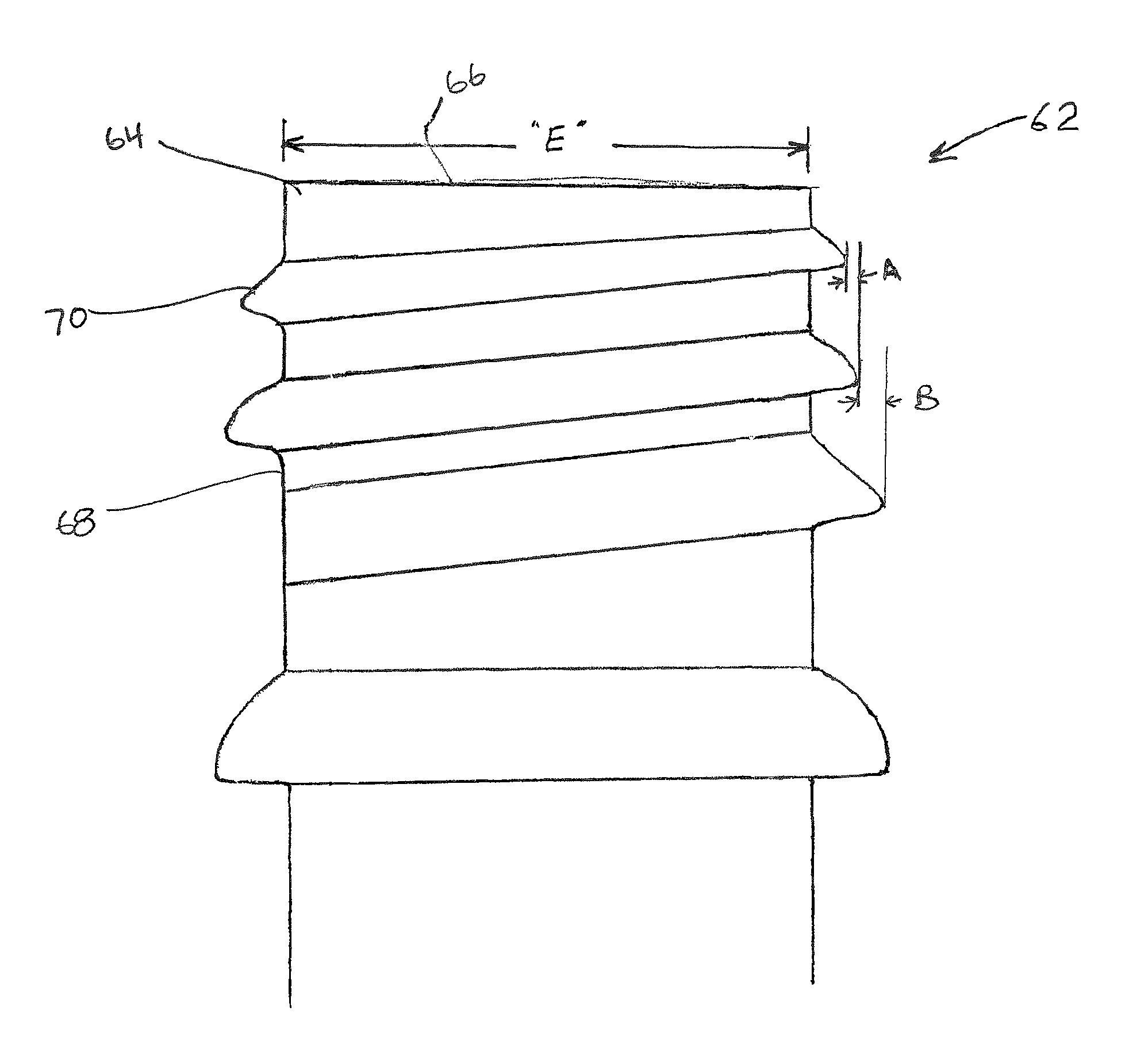
[0011]In the present invention, a unique neck finish for a container is provided. The neck finish includes a substantially cylindrical exterior wall surface surrounding an orifice defined in the container and includes a thread structure positioned about the exterior wall surface. The thread structure has at least a first portion and a second portion. Each portion has a corresponding effective maximum diameter, wherein the effective maximum diameter of the first portion is less than the effective maximum diameter of the second portion.

[0012]Further elements of the first embodiment may include providing a neck finish wherein the first portion is positioned axially above the second portion. Alternatively, the thread structure may have a convex surface projecting radially outwardly from the exterior wall surface. The thread structure may also have an effective maximum diameter that continuously increases from the first portion to the second portion, or that incrementally increases from ...

second embodiment

[0013]In the present invention a neck finish for a container is provided and has a substantially cylindrical exterior wall surface surrounding an orifice and has a thread structure. The thread structure has multiple portions of convex surface regions projecting radially outwardly from the exterior wall surface. Each of the portions has a point of maximum separation from the exterior wall surface. The point of maximum separation also defines an effective maximum diameter associated with the portion. A selected first portion has an effective maximum diameter less than a selected second portion positioned axially below the first portion.

[0014]Additional elements of the second embodiment may provide for multiple portions being positioned to form a helical path extending circumferentially around the exterior wall surface and being characterized by having a maximum effective diameter of a portion positioned at an upper segment of the helical path being less than the maximum effective diam...

third embodiment

[0015]In the present invention a neck finish for a container is provided in combination with a container closure. The neck finish is defined as having an upper orifice that defines an opening, a downward extending neck wall below the opening, a thread structure positioned on the exterior of the neck wall, and a first bead-like structure surrounding the neck wall positioned axially below the thread structure. The thread structure has a first portion and a second portion positioned axially below the first portion. The first and second portions have a corresponding effective maximum diameter such that the effective maximum diameter of the first portion is less than the effective maximum diameter of the second portion. The container closure has a top, a downwardly extending skirt portion depending from the top. The skirt portion has an interior, and a radially inwardly projecting member adapted for engagement with the first bead-like structure, such as a second bead-like structure or a ...


PUM


Abstract

In one embodiment there is provided a novel container neck finish having a substantially cylindrical exterior wall surface surrounding an orifice defined in the container and a thread structure positioned about the exterior wall surface. The thread structure has at least a first portion and a second portion. Each portion has a corresponding effective maximum diameter, wherein the effective maximum diameter of the first portion is less than the effective maximum diameter of the second portion.

Description

FIELD OF THE INVENTION[0001]The present invention relates to tapered thread structures on a container finish and a corresponding closure.BACKGROUND[0002]Thread structures used on containers can take a wide variety of designs. The details of any one particular thread structure on a container is influenced by many factors, including the contained contents, operational aspects of the complimentary closure, materials, methods of package manufacture and consumer use.[0003]A particularly useful and widely accepted closure / seal system for packages is to position external threads on the container which mate with internal threads positioned on the interior wall of a closure. As is well known, the closure is removed and reapplied by rotary threading action.[0004]One factor requiring attention with threaded closure systems is the circumferential extent of mating thread engagement between closure and container. One may desire to minimize circumferential thread engagement to only that required f...

Claims


Application Information

Patent Timeline
IPC IPC(8): B65B7/28B65D39/08
CPCB65D41/3428B65D1/0246
Inventor PETERS, MIKE LYNNLOHRMAN, RICHARD D
Owner PORTOLA PACKING INC
Why Eureka
Try Eureka