Electrical junction and joint box for a solar cell module

a solar cell module and electric junction technology, applied in the direction of coupling device connection, photovoltaic energy generation, photovoltaic cells, etc., can solve the problems of solar cell partial shadowing, reduced power, and parallel connection of solar cells that are not normally used, and achieve simple and reliable connection of thin conductor strips

Inactive Publication Date: 2010-06-15
GUNTHER SPELSBERG GMBH CO
View PDF13 Cites 16 Cited by
  • Summary
  • Abstract
  • Description
  • Claims
  • Application Information

AI Technical Summary

Benefits of technology

[0012]Therefore, an object of the invention is to provide a junction and joint box for a solar cell module with which simple and reliable connection of thin conductor strips routed out of the solar cell module is enabled.
[0014]Therefore, the invention employs a completely new approach with regard to the thin conductor strips used for connection of the solar cells and routed out of the solar cell module. Specifically, when the junction and joint box is seated on the solar cell module, the thin conductor strips are, on one hand, routed automatically, without additional manual effort, and on the other hand, directly from underneath, into the electrical connection device. The invention thus avoids the complex process discussed above which routes the thin conductor strips for connection of the solar cells in the junction and joint box first up and than bends them by 180° in order to supply then to the connection device. When the solar cells of the solar cell module are connected, the required effort is therefore greatly reduced by the invention and especially almost no improper contact-making occurs.
[0016]The connection device can be arranged in the housing of the electrical junction and joint box such that the thin conductor strips routed out of the solar cell module, when the junction and joint box is seated on the solar cell module, are routed automatically from underneath into the electrical connection device without there being additional means which support the routing of the conductor strips into the connection device. According to one exemplary embodiment of the invention, located underneath the clamping means is a guide means for guided insertion of the thin conductor strips into the clamping means when the junction and joint box is seated on the solar cell module. The guide means is used essentially to prevent kinking or folding of the conductor strips during insertion. The force of the conductor strips acting in the lengthwise direction (of the thin conductor strips) when they are inserted into the connection device also acts in the desired direction and does not lead to deformation. The guide means includes openings which correspond to the cross sectional dimensions of the thin conductor strips so that when the junction and joint box is seated on the solar cell module the thin conductor strips are routed in these openings with little play. The inside walls of the openings therefore are used for the actual guidance and thus prevent kinking or folding.
[0017]When the junction and joint box is seated on the solar cell module, the thin conductor strips are routed out of the solar cell module, from underneath, and automatically (without manual manipulation) into the electrical connection device, which reveals another advantage. According to one exemplary development of the invention, the housing has side walls and a cover. The side walls and the cover are made in one piece. In other words, with regard to the electrical junction and joint box it is no longer absolutely necessary to provide a removable cover. Finally, the insertion of the thin conductor strips into the connection device takes place automatically, upon seating of the junction and joint box on the solar cell module, so that the interior of the electrical junction and joint box need not be accessible from the top for connection by hand.

Problems solved by technology

In practice, however, parallel connection of solar cells is not normally used, since an individual solar cell can already deliver a current of a few amperes.
However, a problem can arise when a series connected solar cell module is partially shadowed or obstructed from sunlight, so that a solar cell or individual solar cells of the solar cell module receive less solar radiation, or none at all.
In contrast to shadowing of the solar module uniformly over its entire surface, which leads only to a reduction in power, a specific problem arises when a solar cell is subjected to partial shadowing.
However, if one solar cell is shadowed, it no longer generates any voltage and in practice acts as a diode, in the reverse direction, and opposes the current flow in the solar cell module.
As a result, the entire module can no longer deliver current, so that the entire operation of the solar cell module is adversely affected.
If the voltage is greater than its blocking voltage, a breakdown occurs in the solar cell, and thus, the solar cell is permanently damaged.
Even if the solar cell should not be damaged by the breakdown, in the partially shadowed solar cell, a large power loss is converted so that the shadowed solar cell heats up.
This heat-up can lead to damage on the shadowed solar cell, as well as surrounding solar cells.
This results in that a shadowed solar cell no longer delivers any portion to the total voltage of the solar cell module, but the current flow is nevertheless maintained.
However, this approach is very complex and time-consuming, and connection faults cannot be easily avoided.

Method used


Image

  • Electrical junction and joint box for a solar cell module
  • Electrical junction and joint box for a solar cell module
  • Electrical junction and joint box for a solar cell module

Examples


Embodiment Construction

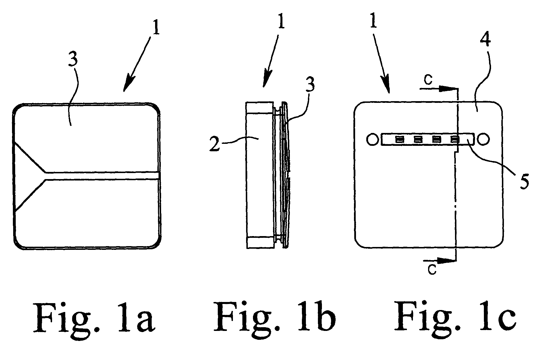
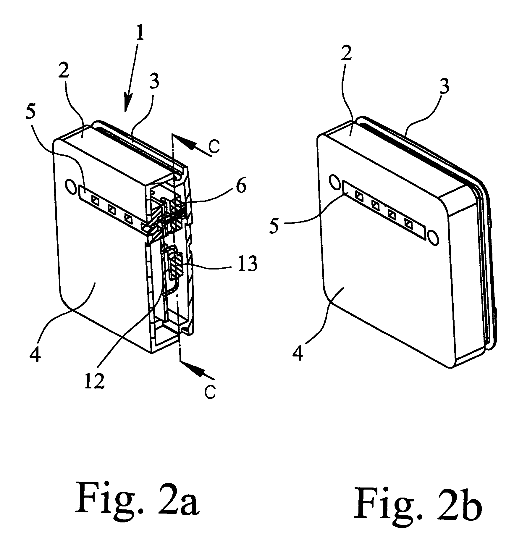
[0025]FIGS. 1a, 1b and 1c illustrate top, side and bottom views, respectively, of an electrical junction and joint box according to a preferred embodiment of the invention. The electrical junction and joint box includes a housing 1 with side walls 2 and a cover 3. Furthermore, a bottom 4 of the housing 1 has an elongated recess 5. As shown in FIG. 2a, a connection device 6, provided in the housing 1, can be reached via the recess 5.

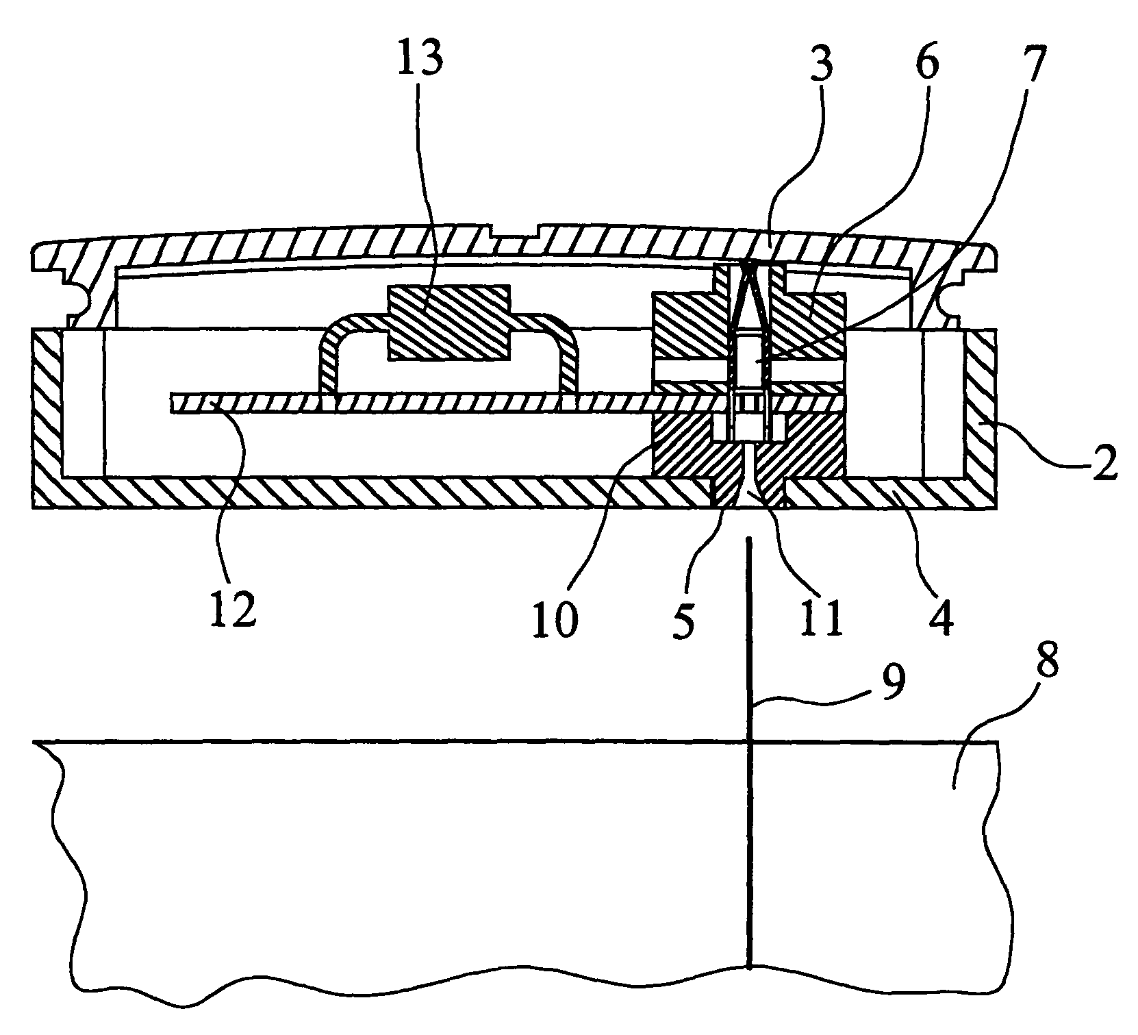
[0026]The structure and arrangement of connection device 6 is described in more detail with reference to FIG. 3, which shows a section through the electrical junction and joint box according to the present invention along line C-C shown in FIG. 1c. FIG. 3 shows that the connection device 6 has a clamping means 7 in the form of two oppositely acting springs. When the junction and joint box is seated, according to the preferred embodiment of the invention, thin conductor strips 9 are routed out of a solar cell module 8 and are automatically inserted into th...


PUM


Abstract

An electrical junction and joint box for a solar cell module having solar cells and an associated method. The junction and joint box and solar cell module are connected by conductor strips. The junction and joint box includes a housing having electrical and / or electronic means and a connection device located in the housing. The connection device is arranged to directly, without manual alteration, receive thin conductor strips routed out of the solar cell module from underneath when the junction and joint box is seated on the solar cell module. In this way reliable and efficient connection of the individual solar cells of the solar cell module can be easily achieved, and faulty contact-making can be avoided.

Description

BACKGROUND OF THE INVENTION[0001]1. Field of the Invention[0002]The present invention is directed to an electrical junction and joint box for use with a solar cell module having solar cells. More specifically, the present invention is directed to an electrical junction and joint box with a housing and electrical and / or electronic means and a connection device provided in the housing.[0003]2. Description of Related Art[0004]Since an output voltage associated with individual solar cells is generally too low to operate electrical devices, such as household appliances or the like, several solar cells are normally interconnected into solar cell modules. On one hand, there is the possibility of series connection of individual solar cells and, on the other, there is the possibility of parallel connection of the solar cells in the solar cell module. The individual currents of the solar cells in parallel connection are added to one another to create an overall current. The solar cells should...

Claims


Application Information

Patent Timeline
Patent Type & Authority Patents(United States)
IPC IPC(8): H01L25/00H01R12/00H01L31/00H01R13/11H02G3/08
CPCH02S40/34Y02E10/50
Inventor NIELECK, UDOQUARDT, DIRKWASSERFUHR, FRIEDELZBOROWSKI, ZBIGNIEW
Owner GUNTHER SPELSBERG GMBH CO
Why Eureka
Try Eureka