Methods, systems, and computer program products for grid-morphing techniques in placement, floorplanning, and legalization

a technology of floorplanning and grid morphing, applied in the field of methods, can solve the problems of undesired waste of computation resources, increased the demand for better optimization of placement algorithms, and the exponential growth of complexity of integrated circuit designs, so as to achieve the effect of minimizing the perturbation of placement, avoiding the need for re-planning, and maintaining the stability of placemen

Inactive Publication Date: 2010-06-15
CADENCE DESIGN SYST INC +1
View PDF7 Cites 15 Cited by
  • Summary
  • Abstract
  • Description
  • Claims
  • Application Information

AI Technical Summary

Benefits of technology

[0001]Placement remains a critical step in the RTL to GDS II or equivalents synthesis process. The exponential growth of complexity in integrated circuits designs has dramatically increased the demand for better optimization of the placement algorithms. Recent development of placement algorithms often ignores an important feature of all placement techniques—stability and thus leads to undesired waste of computation resources.
[0002]A placement tool is considered to offer stability if, for two starting designs which exhibit only small differences between them, the resulting final designs also have small or limited differences. That is, a small change in the input design results in a small change in the final output. For example, stability is important for an incremental design flow where a circuit designer who introduces small changes to a design will want to obtain a new placement incorporating those changes but with minimal effect on the unchanged portions of the design. Placement tools with good stability may also prevent undesired waste of computational resources and runtime that may increase the cost of the design as well as delay the intended time to market.
[0007]Thus, a need exists for computing a spread of objects over an area such that the final locations of the objects are relatively uniformly spread over the entire area by grid morphing and such that the final locations of the objects are minimally perturbed from their initial starting locations and therefore minimizing the perturbation to the placement of the design features and thus maintaining the stability of the placement.
[0008]The present invention transforms a grid superposed on the placement area to another grid and subsequently re-computes the locations of the gates based on that transformation. One of the advantages of the grid morphing technique is that the computation for the new locations of the gates can be done more quickly. Another advantage of the grid morphing technique is the minimal or even no overlapping due to smoothly moving cells while preserving the relative positions of the cells during the grid morphing process to spread the gates. Moreover, some embodiments of the invention may incorporate various characteristics of the design in the grid morphing objective functions and / or the solver without significant increase in runtime overhead.BRIEF

Problems solved by technology

The exponential growth of complexity in integrated circuits designs has dramatically increased the demand for better optimization of the placement algorithms.
Recent development of placement algorithms often ignores an important feature of all placement techniques—stability and thus leads to undesired waste of computation resources.
That is, a small change in the input design results in a small change in the final output.
There are several existing approaches to address the overall placement problem, yet none of which have emphasized placement stability.
Some of these approaches start by computing an initial placement, which may not be feasible in that many gates overlap each other.
Such techniques have a drawback in that small changes to the starting netlist may result in large changes to the final result.
Such instability leads to relatively unpredictable performance of such algorithms.
This key drawback to this approach is that it is difficult to determine a suitable magnitude of force necessary to resolve any particular overlap which can lead to excessive computational complexity and runtime of the algorithm.
The disadvantage of grid-warping algorithms is the relatively high computational cost and runtime involved.

Method used


Image

  • Methods, systems, and computer program products for grid-morphing techniques in placement, floorplanning, and legalization
  • Methods, systems, and computer program products for grid-morphing techniques in placement, floorplanning, and legalization
  • Methods, systems, and computer program products for grid-morphing techniques in placement, floorplanning, and legalization

Examples


Embodiment Construction

[0021]The present invention is directed to an improved methods, system, and computer program product for the placement of objects in a predefined area by grid morphing. As noted above, conventional methods and systems oftentimes ignore placement stability and thus cause unnecessary and undesired waste of runtime and computation resources.

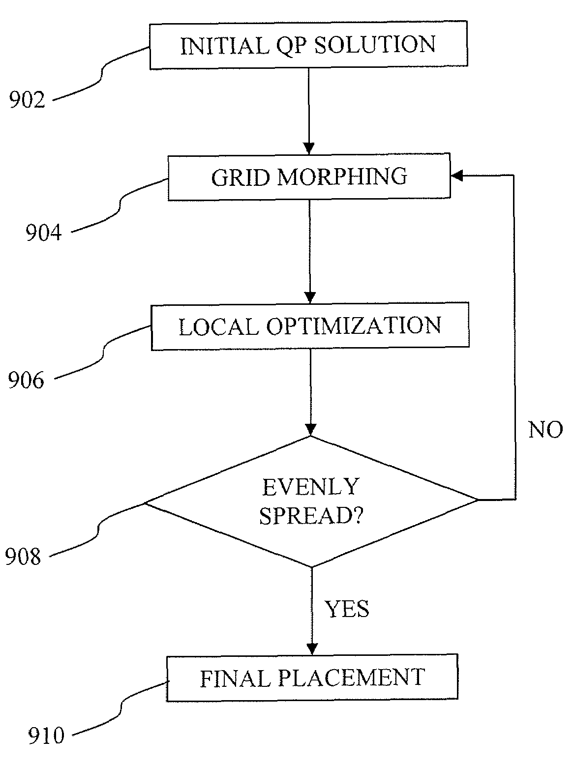
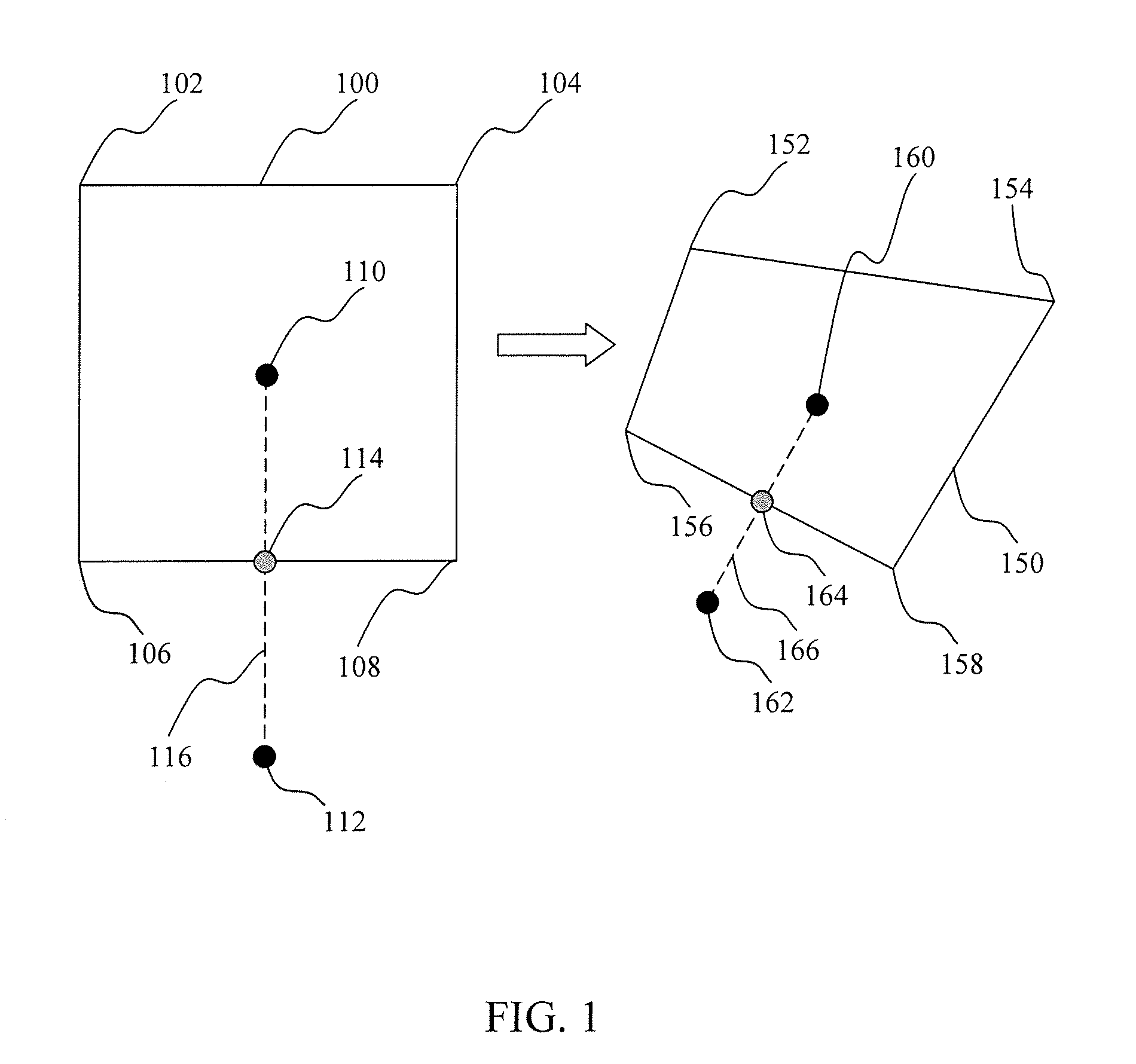
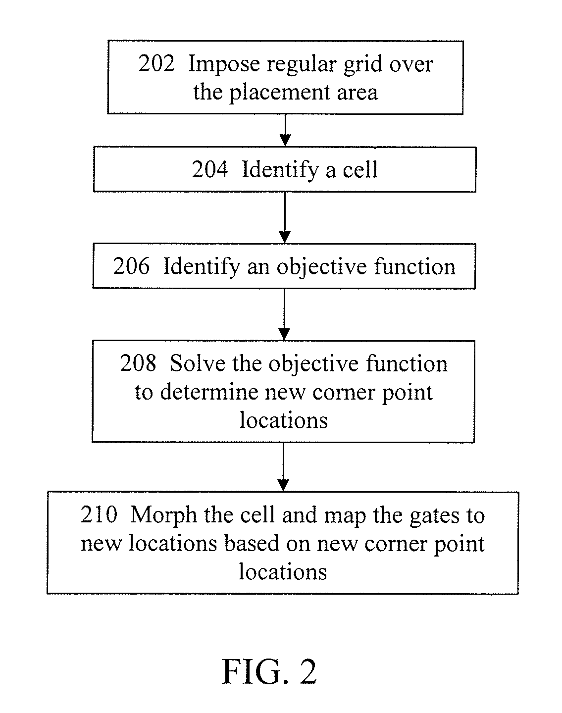
[0022]According to some embodiments, the placement tool imposes a regular grid over the placement area, identifies a cell and an objective function, minimizes the objective function to determine the new locations of the cell after the grid morphing process, and then morph the cell and map the gates or other design features within the cell according to the new locations of the cell.

[0023]Yet some other embodiments use a pressure-based solver to determine the new locations of the cell after grid morphing. Yet some other embodiments further define sensitivity of a characteristic of the design with respect to the geometric changes of the cell and modify...


PUM


Abstract

Disclosed are methods, systems, and computer program products for performing grid morphing technique for computing a spreading of objects over an area such that the final locations of the objects are distributed over the area and such that the final locations of the objects are minimally perturbed from their initial starting locations and the density of objects meets certain constraints. The minimization of perturbation, or stability, of the approaches disclosed, is the key feature which is the principal benefit of the techniques disclosed. The methods described herein may be used as part of a tool for placement or floorplanning of logic gates or larger macroblocks for the design of an integrated circuit.

Description

BACKGROUND AND SUMMARY[0001]Placement remains a critical step in the RTL to GDS II or equivalents synthesis process. The exponential growth of complexity in integrated circuits designs has dramatically increased the demand for better optimization of the placement algorithms. Recent development of placement algorithms often ignores an important feature of all placement techniques—stability and thus leads to undesired waste of computation resources.[0002]A placement tool is considered to offer stability if, for two starting designs which exhibit only small differences between them, the resulting final designs also have small or limited differences. That is, a small change in the input design results in a small change in the final output. For example, stability is important for an incremental design flow where a circuit designer who introduces small changes to a design will want to obtain a new placement incorporating those changes but with minimal effect on the unchanged portions of t...

Claims


Application Information

Patent Timeline
Patent Type & Authority Patents(United States)
IPC IPC(8): G06F17/50
CPCG06F17/5072G06F30/392
Inventor CHONG, PHILIPSZEGEDY, CHRISTIAN
Owner CADENCE DESIGN SYST INC
Why Eureka
Try Eureka