Rope structure with improved bending fatigue and abrasion resistance characteristics

a technology of abrasion resistance and bending fatigue, applied in the field of ropes, can solve the problems of affecting the performance of the lifting line, subjected to bending fatigue and abrasion, etc., and achieve the effects of reducing friction between adjacent fibers

Active Publication Date: 2010-06-22
SAMSON ROPE TECH
View PDF5 Cites 21 Cited by
  • Summary
  • Abstract
  • Description
  • Claims
  • Application Information

AI Technical Summary

Benefits of technology

[0008]The present invention may be embodied as a rope structure adapted to engage an external structure comprising a primary strength component and a coating. The primary strength component comprises a plurality of fibers. The coating comprises a lubricant portion and a binder portion that fixes the lubricant portion relative to at least some of the fibers. The coating is applied to the primary strength component such that the lubricant portion reduces friction between adjacent fibers and reduces friction between fibers and the external structure.
[0009]The present invention may also be embodied as a method of forming a rope structure ad

Problems solved by technology

When loads are applied to the lifting line, the lifting line wraps around such intermediate structural members and is thus subjected to bending fatigue and abrasion at the intermediate structural members.
Abrasion and heat generat

Method used


Image

  • Rope structure with improved bending fatigue and abrasion resistance characteristics
  • Rope structure with improved bending fatigue and abrasion resistance characteristics
  • Rope structure with improved bending fatigue and abrasion resistance characteristics

Examples


first specific rope example

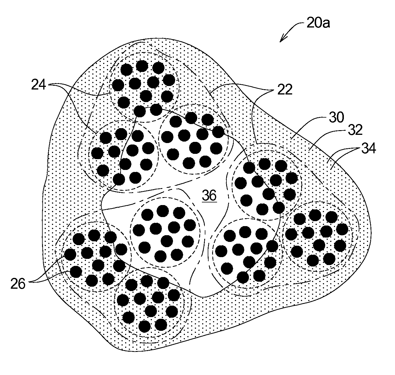
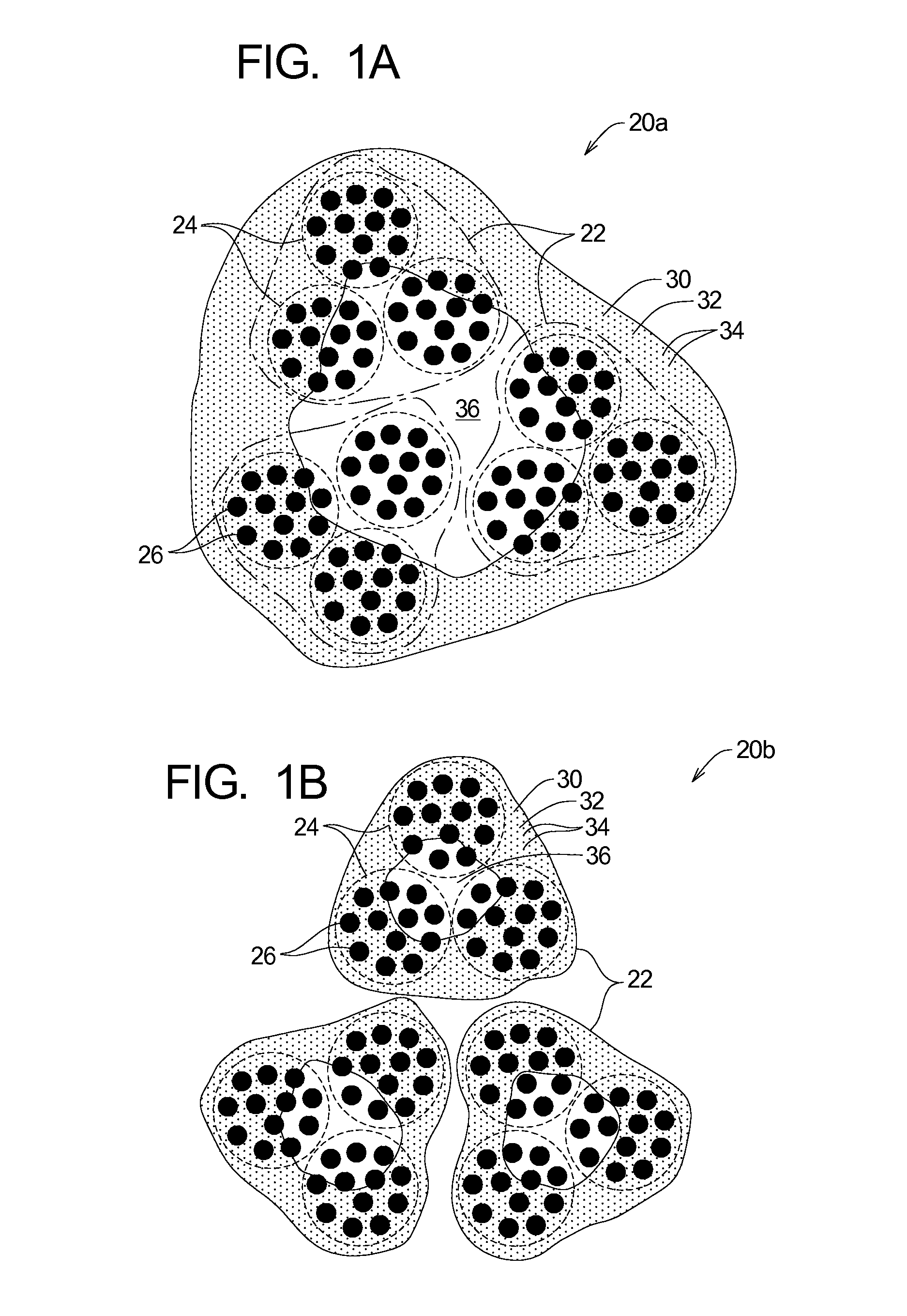
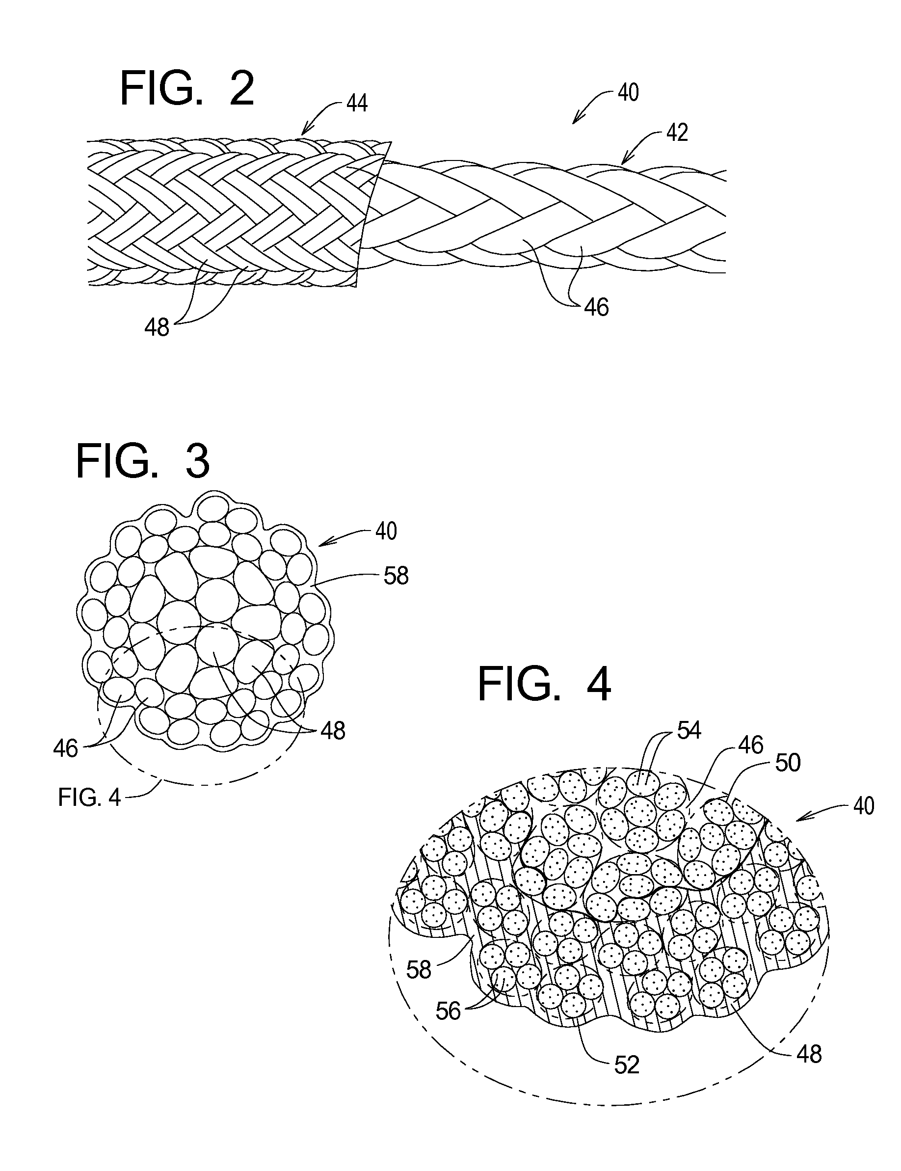
[0037]Referring now to FIGS. 2, 3, and 4, those figures depict a first specific example of a rope 40 constructed in accordance with the principles of the present invention. As shown in FIG. 2, the rope 40 comprises a rope core 42 and a rope jacket 44. FIG. 2 also shows that the rope core 42 and rope jacket 44 comprise a plurality of strands 46 and 48, respectively. FIG. 4 shows that the strands 46 and 48 comprise a plurality of yarns 50 and 52 and that the yarns 50 and 52 in turn each comprise a plurality of fibers 54 and 56, respectively. FIGS. 3 and 4 also show that the rope 40 further comprises a coating material 58 that forms a matrix that at least partially surrounds at least some of the fibers 54 and 56.

[0038]The exemplary rope core 42 and rope jacket 44 are formed from the strands 46 and 48 using a braiding process. The example rope 40 is thus the type of rope referred to in the industry as a double-braided rope. The strands 46 and 48 may be substantially identical in size an...

second rope example

[0039]Referring now to FIGS. 5, 6, and 7, those figures depict a second example of a rope 60 constructed in accordance with the principles of the present invention. As perhaps best shown in FIG. 6, the rope 60 comprises a plurality of strands 62. FIG. 7 further illustrates that each of the strands 62 comprises a plurality of yarns 64 and that the yarns 64 in turn comprise a plurality of fibers 66. FIGS. 6 and 7 also show that the rope 60 further comprises a coating material 68 that forms a matrix that at least partially surrounds at least some of the fibers 66.

[0040]The strands 62 are formed by combining the yarns 64 using any one of a number of processes. The exemplary rope 60 is formed from the strands 62 using a braiding process. The example rope 60 is thus the type of rope referred to in the industry as a braided rope.

[0041]The strands 62 and yarns 64 forming the rope 60 may be substantially identical in size and composition. However, strands and yarns of different sizes and com...

third rope example

[0042]Referring now to FIGS. 8, 9, and 10, those figures depict a third example of a rope 70 constructed in accordance with the principles of the present invention. As perhaps best shown in FIG. 9, the rope 70 comprises a plurality of strands 72. FIG. 10 further illustrates that each of the strands 72 comprises a plurality of yarns 74, respectively. The yarns 74 are in turn comprised of a plurality of fibers 76. FIGS. 9 and 10 also show that the rope 70 further comprises a coating material 78 that forms a matrix that at least partially surrounds at least some of the fibers 76.

[0043]The strands 72 are formed by combining the yarns 74 using any one of a number of processes. The exemplary rope 70 is formed from the strands 72 using a twisting process. The example rope 70 is thus the type of rope referred to in the industry as a twisted rope.

[0044]The strands 72 and yarns 74 forming the rope 70 may be substantially identical in size and composition. However, strands and yarns of differe...


PUM

PropertyMeasurementUnit
Fractionaaaaaaaaaa
Percent by massaaaaaaaaaa

Abstract

A rope structure adapted to engage an external structure comprising a primary strength component and a coating. The primary strength component comprises a plurality of fibers. The coating comprises a lubricant portion and a binder portion that fixes the lubricant portion relative to at least some of the fibers. The coating is applied to the primary strength component such that the lubricant portion reduces friction between adjacent fibers and reduces friction between fibers and the external structure.

Description

RELATED APPLICATIONS[0001]This application claims priority of U.S. Provisional Patent Application Ser. No. 60 / 717,627 filed Sep. 15, 2005, the contents of which are incorporated herein by reference.TECHNICAL FIELD[0002]The present invention relates to rope systems and methods and, in particular, to ropes that are coated to improve the resistance of the rope to bending fatigue.BACKGROUND OF THE INVENTION[0003]The characteristics of a given type of rope determine whether that type of rope is suitable for a specific intended use. Rope characteristics include breaking strength, elongation, flexibility, weight, bending fatigue resistance and surface characteristics such as abrasion resistance and coefficient of friction. The intended use of a rope will determine the acceptable range for each characteristic of the rope. The term “failure” as applied to rope will be used herein to refer to a rope being subjected to conditions beyond the acceptable range associated with at least one rope ch...

Claims


Application Information

Patent Timeline
IPC IPC(8): D02G3/02
CPCD07B1/142D07B1/162D07B2201/104D07B2201/1096Y10T428/24612D07B2205/507D07B2205/2071D07B2801/16
Inventor CHOU, CHIA-TESTENVERS, DANIELLE D.MILLER, JONATHAN D.
Owner SAMSON ROPE TECH
Why Eureka
Try Eureka