
Vehicle surroundings monitoring apparatus and traveling control system incorporating the apparatus

a technology of vehicle surroundings and monitoring apparatus, which is applied in the direction of anti-collision systems, external condition input parameters, special data processing applications, etc., can solve problems such as the failure of the preceding vehicle detection

Active Publication Date: 2010-06-22
SUBARU CORP
View PDF24 Cites 155 Cited by
  • Summary
  • Abstract
  • Description
  • Claims
  • Application Information

AI Technical Summary

Benefits of technology

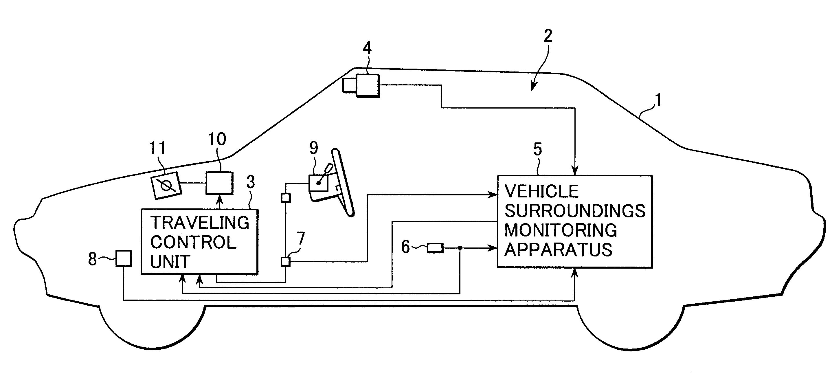
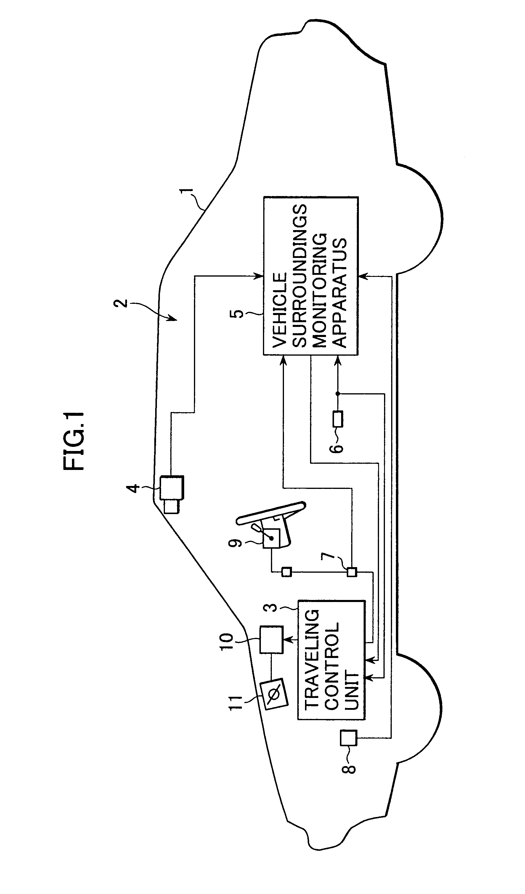
The present invention provides a vehicle surroundings monitoring apparatus that can quickly and securely detect a preceding vehicle and make a traveling control system that takes the preceding vehicle into consideration in a natural manner similar to drivers' senses. This apparatus includes a vehicle traveling conditions detecting means, a vehicle forward information detecting means, a traveling path estimating means, and a judging means to determine if the solid object is a preceding vehicle, a tentative preceding vehicle, or other objects. The traveling control system performs constant speed traveling, follow-up traveling, and other traveling controls based on the preceding vehicle information extracted by the vehicle surroundings monitoring apparatus.

Problems solved by technology

However, the disadvantage of the prior art is that since the judgment of a preceding vehicle is dependent upon the estimated lateral position of a solid object at the own lane region, if the estimation differs, the detection of the preceding vehicle may fail.

Method used


Image

  • Vehicle surroundings monitoring apparatus and traveling control system incorporating the apparatus
  • Vehicle surroundings monitoring apparatus and traveling control system incorporating the apparatus
  • Vehicle surroundings monitoring apparatus and traveling control system incorporating the apparatus

Examples


first embodiment

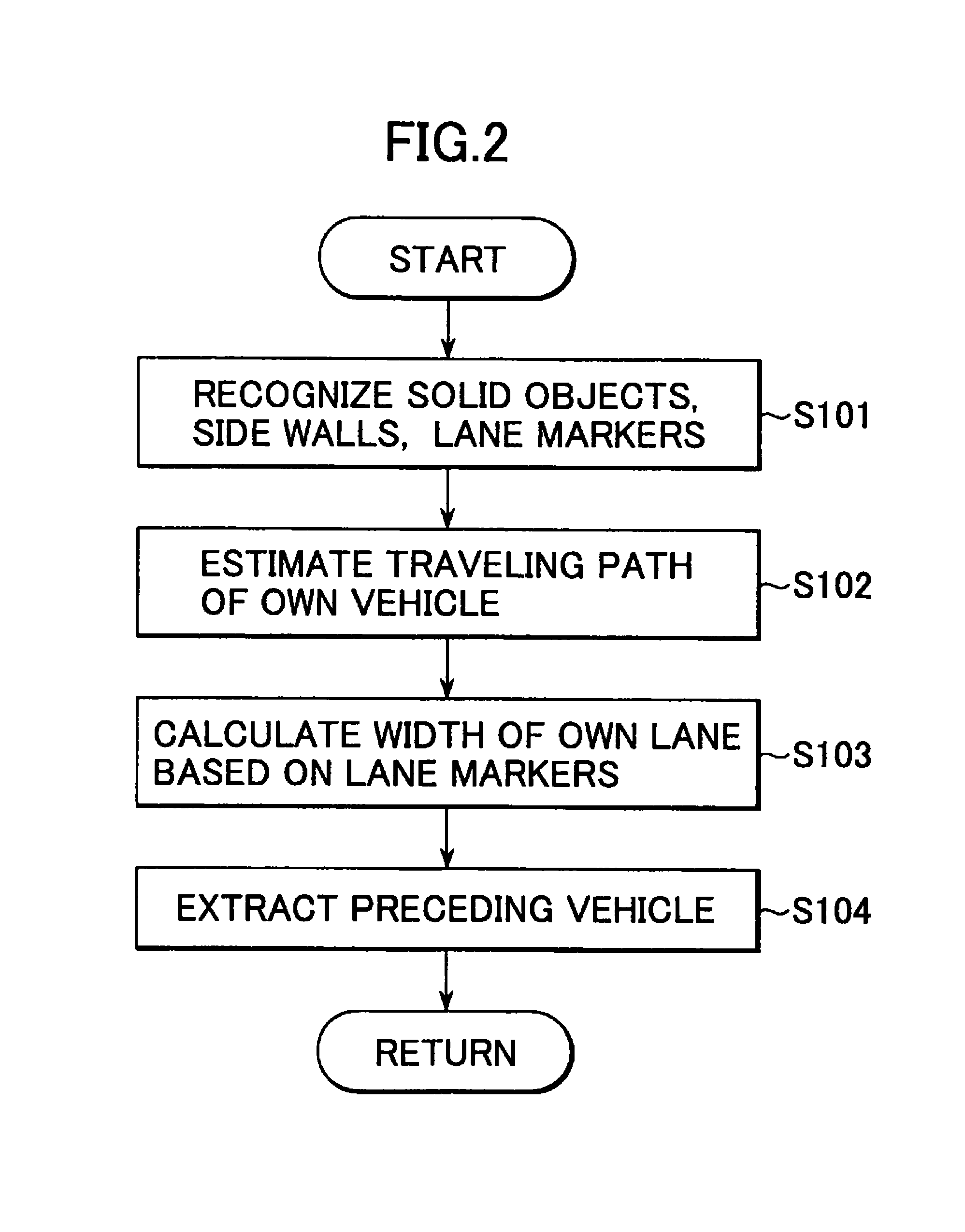
[0116]The flowchart of the preceding vehicle extracting routine shown in FIG. 4 is modified as shown in FIG. 11. In accordance with the flowchart of FIG. 11, after the traveling regions A, B are established at S302, the program goes to S701 where it is judged whether or not the solid object exists in the traveling region A. In case where the solid object exists in the traveling region A, the program goes to S702 where the count value TIAcl is counted up by 2 (TIAcl=TIAcl+2) and goes to S306.

[0117]Further, in case where it is judged at S701 that the solid object does not exist in the traveling region A, the program goes to S703 where it is judged whether or not the solid object exists in the traveling region B. As a result of the judgment of S703, if the solid object exists in the traveling region B, the program goes to S704 where the count value TIAcl of the traveling region intrusion timer is counted up by 1 (TIAcl=TIAcl+1) and goes to S306.

[0118]On the other hand, as a result of ...

second embodiment

[0119]Thus, according to the present invention, since when the solid object exists in the traveling region A, the traveling region intrusion timer counts up faster than when the solid object exists in the traveling region B, the preceding vehicle can be registered in a manner more similar to actual sense of recognition by a driver.

[0120]In the first and second embodiments, vehicle forward information is obtained from the stereoscopic camera 4, however it may be obtained from other information acquiring means, such as a combination of monocular camera and laser radar or a combination of monocular camera and infrared radar.


PUM


Abstract

A vehicle surroundings monitoring apparatus inputs signals indicative of images from a stereoscopic camera, a vehicle speed, a steering wheel angle and a yaw rate and estimates a traveling path of an own vehicle according to vehicle forward information and traveling conditions of the own vehicle. The apparatus establishes a traveling region A according to this traveling path and further establishes a traveling region B based on at least either of the traveling region A and road information. It is judged whether a detected solid object is a preceding vehicle or a tentative preceding vehicle according to the state of existence of the object in the traveling regions A, B and the preceding vehicle is outputted to a traveling control unit.

Description

[0001]The disclosure of Japanese Patent Application No. 2002-259173 filed on Sep. 4, 2002 including the specification, drawings and abstract is incorporated herein by reference in its entirety.BACKGROUND OF THE INVENTION[0002]1. Field of the Invention[0003]The present invention relates to a vehicle surroundings monitoring apparatus for detecting a preceding vehicle existing ahead of an own vehicle from traveling circumstances in front of the own vehicle detected by a stereoscopic camera, a monocular camera, a millimeter wave radar, and the like and to a traveling control system incorporating such vehicle surroundings monitoring apparatus.[0004]2. Discussion of Related Arts[0005]In recent years, such a traveling control system as detecting traveling circumstances by a camera and the like mounted on a vehicle, recognizing a preceding vehicle from the traveling circumstances data and making a control to follow up the preceding vehicle or to keep an intervehicle distance between the own...

Claims


Application Information

Patent Timeline
Patent Type & Authority Patents(United States)
IPC IPC(8): G01S13/93B60R21/00B60K31/00G01S17/931B60W30/00B60W30/16F02D29/02G01S17/86G08G1/16
CPCB60K31/0008G01S17/936B60W2550/20G01S17/023B60W2550/306G01S17/86G01S17/931B60W2554/00B60W2554/4041B60W2554/802B60W2554/4044
Inventor SEKIGUCHI, HIROYUKI
Owner SUBARU CORP
Learn More