Wiper device, especially for a motor vehicle

a wiper device and motor vehicle technology, applied in the direction of vehicle cleaning, roof, ways, etc., can solve the problems of high cost, easy injury of pedestrians, and high cost, and achieve the effect of improving damping and increasing connection strength

Inactive Publication Date: 2010-06-29
ROBERT BOSCH GMBH
View PDF9 Cites 41 Cited by
  • Summary
  • Abstract
  • Description
  • Claims
  • Application Information

AI Technical Summary

Benefits of technology

[0004]The windshield wiper device in accordance with the invention has the advantage that the windshield wiper device can be fixed in the simplest manner to the body of the motor vehicle by a rotational connection with a locking element. A rotational connection does not require any threads and can be closed by a rotation less than 360 degrees. As a result, the number of work steps before and during assembly can be reduced and the costs during manufacturing and assembly are reduced. In addition, a predetermined breaking point in the locking element allows simple and cost-effective pedestrian impact protection to be realized.
[0005]It is especially advantageous if the rotational connection features a catch, which serves as an orientation for the locking element and locks said locking element into a preferred position. The connection strength is increased in this way so that the connection will not detach by itself even in the case of strong, longer lasting vibrations like those that constantly occur when operating a vehicle. However, because of the predetermined breaking point, detachment of the connection in the case of a pedestrian impact on the wiper shafts of the windshield wiper device is guaranteed in spite of this.

Problems solved by technology

This is relatively expensive and cost-intensive since bore holes provided with threads have to be attached to the body of the motor vehicle or holes have to be provided onto which a screw nut has to be welded.
In addition, the windshield wiper device is very solidly connected with the body of the vehicle and this means that a pedestrian can be easily injured in an impact with the engine hood of the motor vehicle by the wiper shafts projecting from the body, which bear the wiper arms and wiper blades.

Method used


Image

  • Wiper device, especially for a motor vehicle
  • Wiper device, especially for a motor vehicle
  • Wiper device, especially for a motor vehicle

Examples


Embodiment Construction

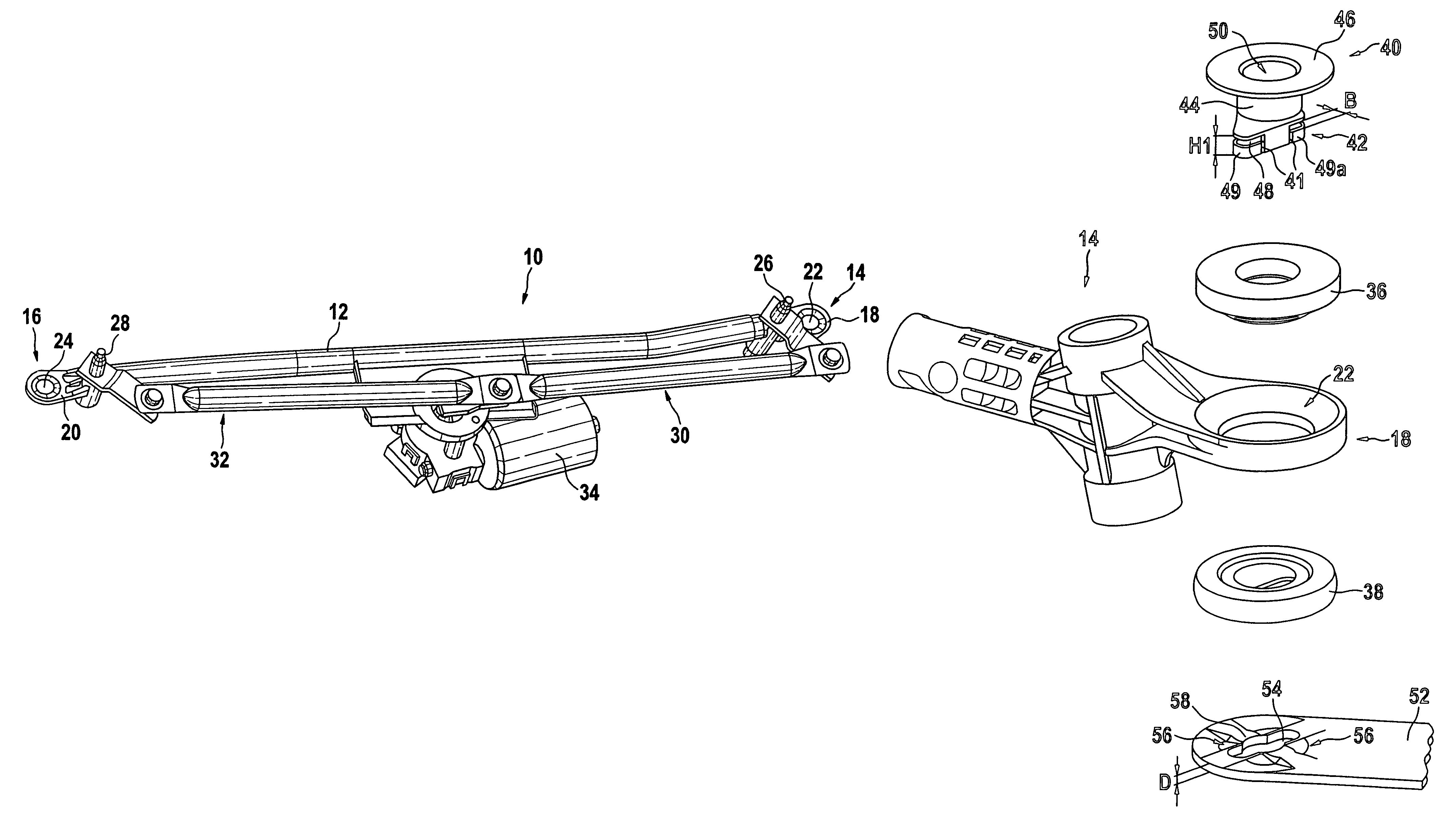
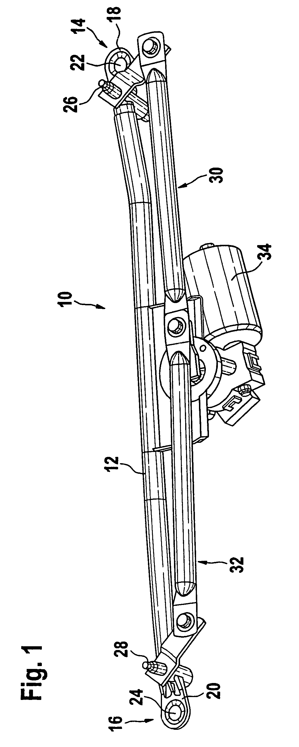
[0020]FIG. 1 shows a schematic depiction of a windshield wiper device 10 in accordance with the invention. It essentially includes a carrier 12 consisting of a tube with a wiper bearing 14, 16 arranged on each of its ends. Each wiper bearing 14, 16 features ears 18, 20 and each of these ears has an opening 22, 24. Furthermore, wiper shafts 26, 28, which are connected to wiper arms (not shown in this case), are positioned in the wiper bearings 14, 16. The wiper shafts 26, 28 are driven via a crank mechanism 30, 32, which is put into motion by a motor 34.

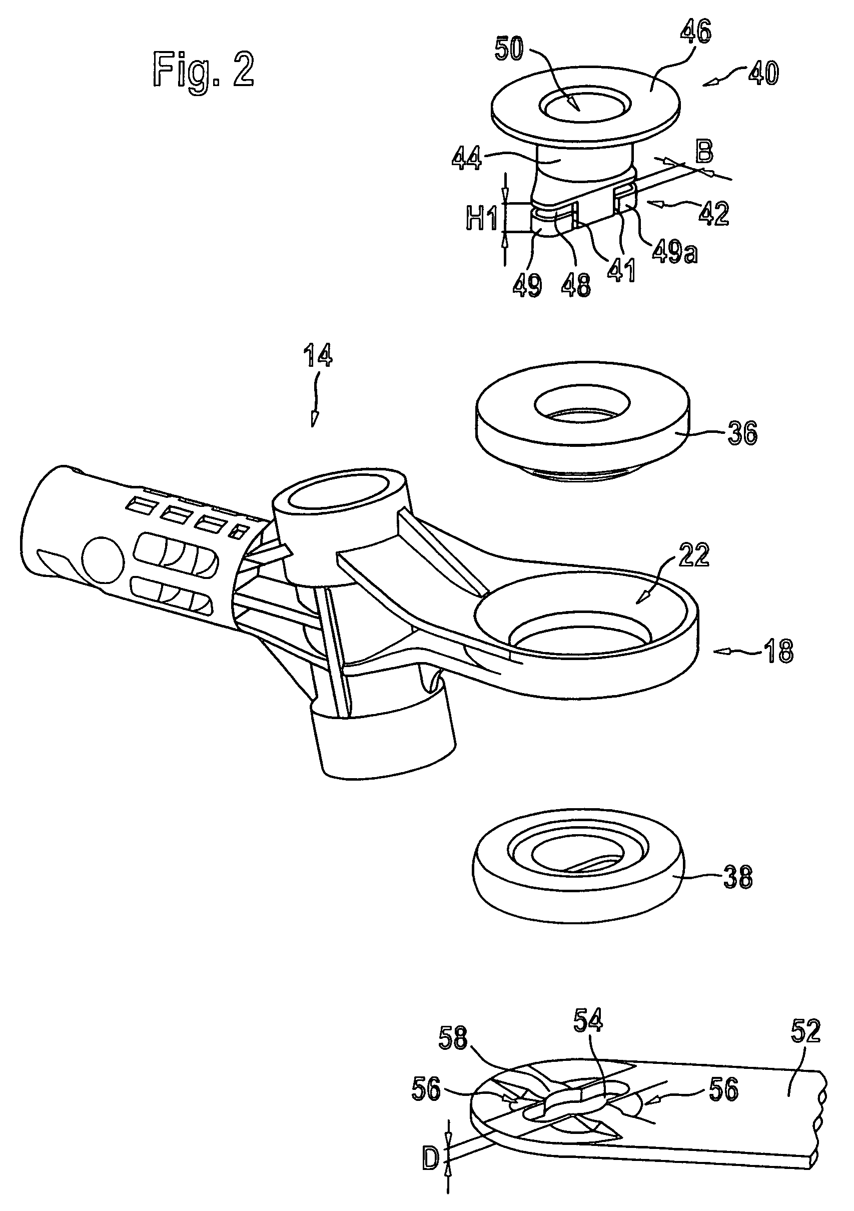
[0021]FIG. 2 shows an exploded representation of a wiper bearing of a windshield wiper device in accordance with the invention. As a part of the carrier 12, the wiper bearing 14 has an ear 18 with an opening 22. The damping bushing 36, 38, which is designed as two parts in this case, is inserted into the opening 22. Of course, it is also conceivable to design the bushing 36, 38 as one piece. The damping bushings 36, 38 are embodied as...


PUM


Abstract

A windshield wiper device, in particular for a motor vehicle, comprising a carrier (12) for fixing to a first part (52), especially to the body of the motor vehicle. A locking element (40) having a predetermined breaking point (41) is also provided in order to enable the carrier (12) to be fixed to the first part (52) by a rotational connection.

Description

BACKGROUND OF THE INVENTION[0001]The invention relates to a windshield wiper device, in particular for a motor vehicle.[0002]Numerous windshield wiper devices featuring a carrier, which is fixed to a first part, for example the body of a motor vehicle, are already known. Normally, the carrier has openings through which screws or rivets can be drawn so that the windshield wiper device can be screwed down to the body with the aid of several screws and various damping elements. This is relatively expensive and cost-intensive since bore holes provided with threads have to be attached to the body of the motor vehicle or holes have to be provided onto which a screw nut has to be welded.[0003]In addition, the windshield wiper device is very solidly connected with the body of the vehicle and this means that a pedestrian can be easily injured in an impact with the engine hood of the motor vehicle by the wiper shafts projecting from the body, which bear the wiper arms and wiper blades.SUMMARY...

Claims


Application Information

Patent Timeline
Patent Type & Authority Patents(United States)
IPC IPC(8): B60S1/06B60S1/04F16B21/02F16B21/09
CPCB60S1/0447B60S1/0488F16B21/09F16B21/02B60S1/0433Y10T403/7005Y10S403/03Y10T403/11F16B2200/63B60S1/04
Inventor METZ, ULRICH
Owner ROBERT BOSCH GMBH
Why Eureka
Try Eureka