Multi-function power monitor and circuit protector

a multi-functional, power monitor technology, applied in the direction of circuit arrangements, emergency protective circuit arrangements, electrical equipment, etc., can solve the problems of abnormal power conditions, abnormal power conditions may arise within the facility itself, and interruption of use or failure of products

Inactive Publication Date: 2005-11-03
TANIS JAMES
View PDF7 Cites 55 Cited by
  • Summary
  • Abstract
  • Description
  • Claims
  • Application Information

AI Technical Summary

Benefits of technology

[0017] As a further aspect of the invention, the integral unit has the ability to assign more than one output relay to a specific sensing circuit or more than one sensing circuit to a specific output relay, eliminating the restriction of having just one For

Problems solved by technology

With the rapid advancement of technology, electrical and electronic products used in such facilities have become quite sensitive to abnormal power conditions, which may cause interruption in use or failure of the products.
Abnormal power conditions may arise, for example, from power utility failure in the form of under-voltages, over-voltages, voltage unbalances, phase reversals, phase angle errors or phase losses.
Other abnormal power conditions may occur within a facility itself, such as blown fuses, over-currents, current unbalances or abnormal equipment operating temperature.
To restore power, all of the blown fuses (main fuses and trigger fuses) must be manually replaced, imposing added costs and difficulties in maintaining the system.
However, these dry output contacts have no internal power

Method used


Image

  • Multi-function power monitor and circuit protector
  • Multi-function power monitor and circuit protector
  • Multi-function power monitor and circuit protector

Examples


Embodiment Construction

[0032] A preferred embodiment of the invention is herein described in detail, and is sometimes referred to as a “power protection system”. It is to be understood that while a particular system configuration, circuit layouts, and modes of operation are described, other modifications and variations may be made thereto in accordance with the general principles of the invention disclosed herein.

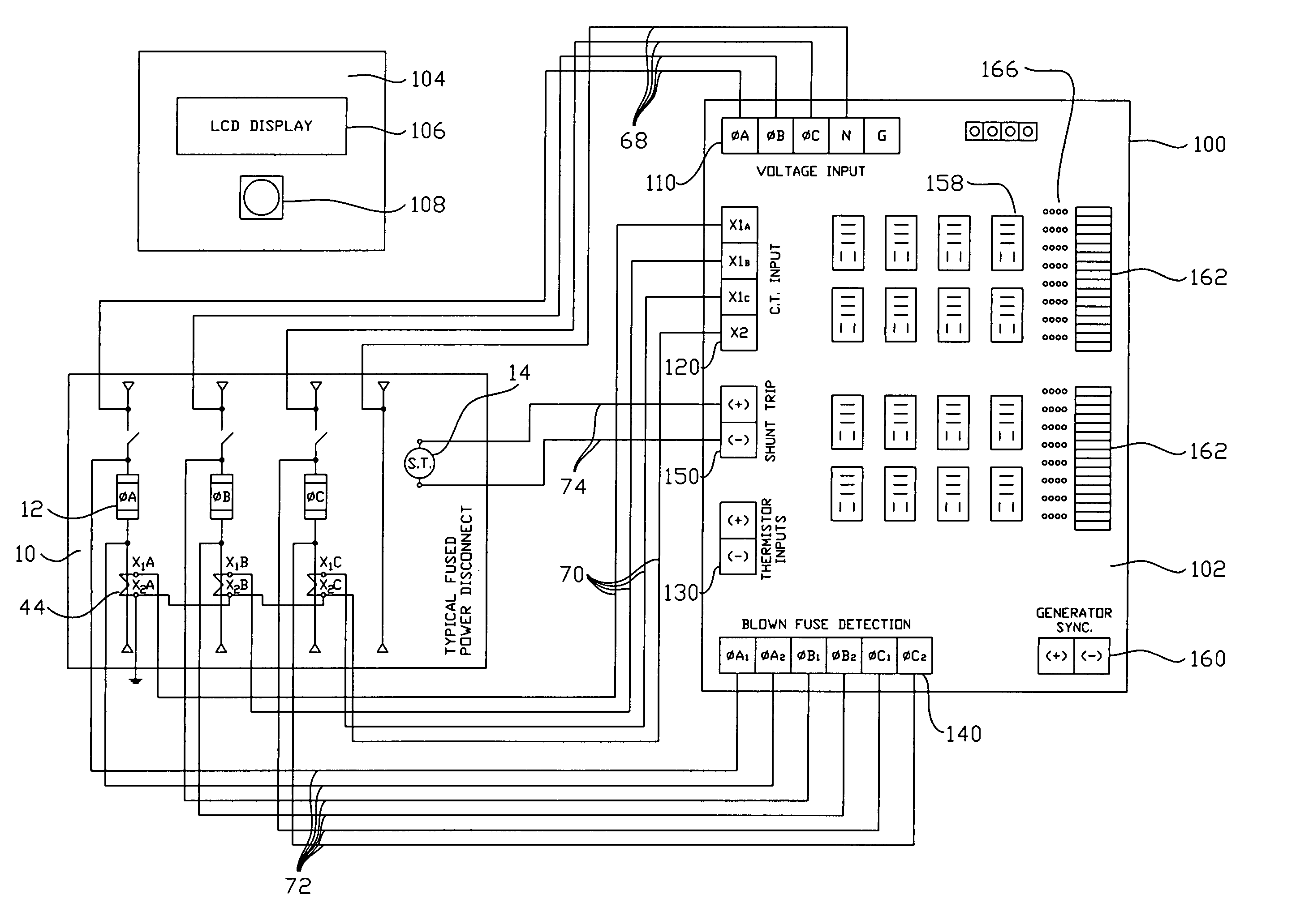
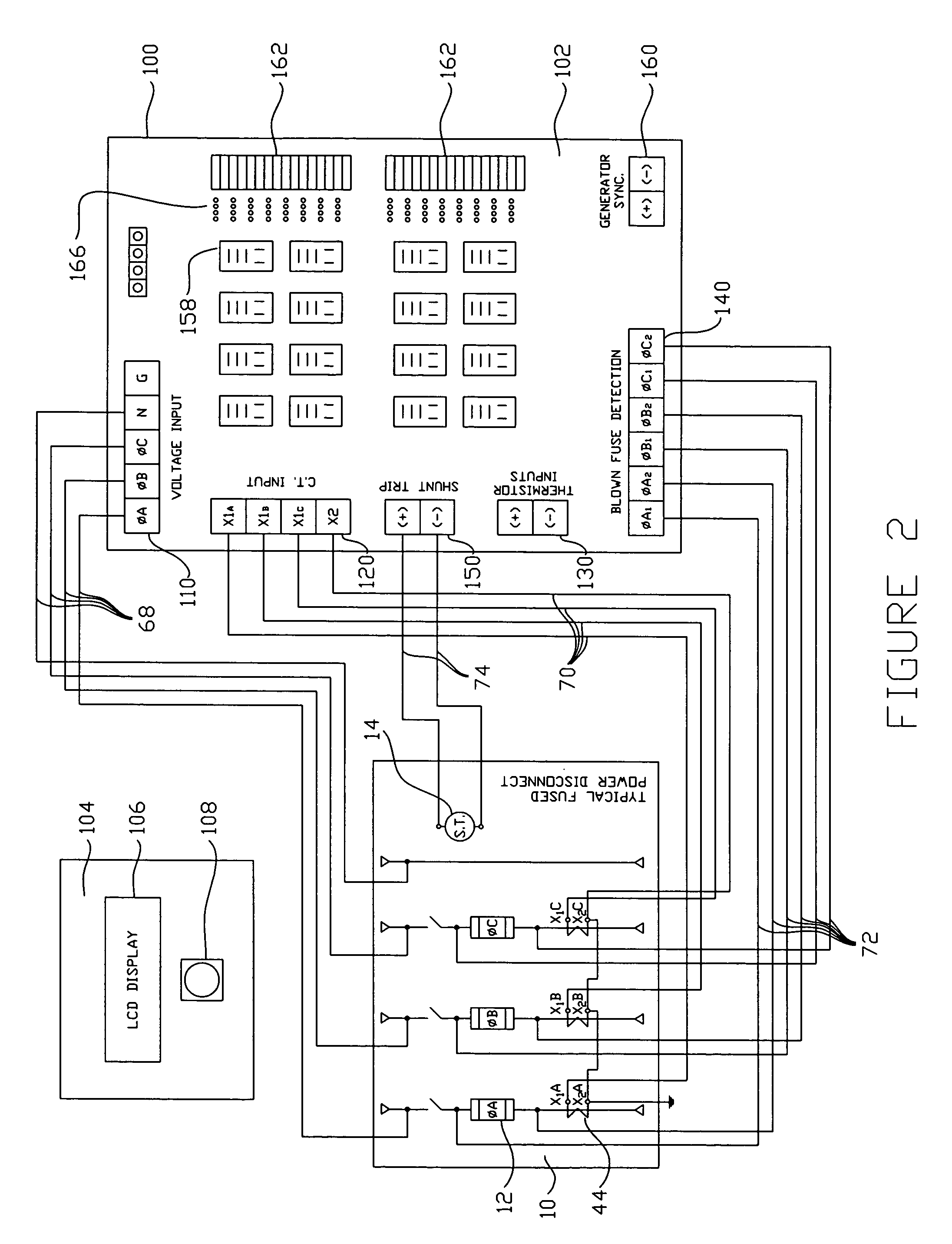
[0033] The power protection system is an integrated electronic system used to monitor the power utilized in a facility for abnormal power conditions and causing a power disconnect switch to open when certain abnormal power conditions are detected. The system may be used to control any of the power disconnect switches in a facility, including the main power disconnect switch and any of the branch disconnect switches. The system includes the functionality of the existing stand-alone power sensing packages described above, as well as other types of power regulation, power monitoring and fault detec...


PUM


Abstract

A compact and multi-functional power monitoring and circuit protection system is provided that is easily installed, used and modified, and internally derives all control and output power from the input voltages being monitored for abnormal power conditions. The functionality of all desired power monitoring and sensing devices is integrated into one unit controlled by a microprocessor. This substantially reduces the number of parts and control wiring required to achieve adequate power monitoring and circuit protection, and reduces the assembly and installation time. The integrated system uses only one set of voltage input wires, one set of current input wires, one set of blown fuse input wires and one output pair of wires to the power disconnect switch's shunt trip. Circuitry is provided to select one of the three power phases being monitored such that one of the three phases is always available to power the system. Control voltages for controlling the shunt trip and external circuits using output relays (to illuminate pilot lights, bell alarms, etc.) are also provided onboard the unit. A blown fuse detection circuit uses solid-state devices in lieu of replaceable trigger fuses. The unit can be instantly reset itself after a blown fuse condition in a power disconnect switch has been rectified.

Description

CROSS REFERENCE TO RELATED APPLICATIONS [0001] This application claims the benefit of U.S. Provisional Patent Application No. 60 / 565,891 filed Apr. 28, 2004, the disclosure of which is incorporated herein by reference.FIELD OF THE INVENTION [0002] This invention relates generally to a power monitoring and circuit protection system, and more particularly, to an integral system having multiple means for monitoring electrical power distribution systems and devices and protecting them against abnormal power conditions. BACKGROUND OF THE INVENTION [0003] Electrical power distribution systems are used to bring electric service from a power utility into facilities such as residential, office and industrial buildings. Typically, the electric service provided by a power utility is in a three phase configuration. Each facility's distribution system includes a number of fused power disconnect switches, which switch power on and off, as well as protect against short circuits and overloads, incl...

Claims


Application Information

Patent Timeline
IPC IPC(8): H02H3/00H02H3/04H02H5/04
CPCH02H3/00H02H5/04H02H3/046
Inventor TANIS, JAMES
Owner TANIS JAMES
Why Eureka
Try Eureka