Stump grinding wheel

a technology of stump grinding and grinding wheel, which is applied in the field of stump grinding wheel, can solve the problems of large areas of the periphery of the wheel unprotected, prone to extreme wear from abrasives, and large areas of the periphery of the wheel being exposed to extreme wear, so as to achieve the effect of improving the positioning, placement and/or orientation of the side cutter assembly and maintaining the optimal cutting performan

Active Publication Date: 2010-06-29
NEW RIVER EQUIP
View PDF9 Cites 31 Cited by
  • Summary
  • Abstract
  • Description
  • Claims
  • Application Information

AI Technical Summary

Benefits of technology

[0015]An objective of the present invention is to provide a stump grinding wheel in which the design of the pockets of the side cutter assemblies enables improved positioning, placement and / or orientation of the side cutter assemblies, thereby protecting from wear the peripheral areas of the wheel, the pockets of the peripheral cutter assemblies and the welds that secure the pockets of the peripheral cutter assemblies, while maintaining optimum cutting performance.
[0016]Another objective of the present invention is to provide a stump grinding wheel in which the design of the pockets of the side cutter assemblies limits interference of the side cutter assemblies with one another and with the welds of the peripheral cutter assemblies, thereby reducing the possibility of clogging the wheel with roots and dirt.
[0018]Still another objective of the present invention is to provide a stump grinding wheel that includes pockets for the side cutter assemblies that are mounted in an orientation which enables a manufacturer to optionally adjust the angle of the side cutter assemblies to achieve a more forward angle, known to those skilled in the art as a positive rake, to allow the side cutter assemblies to cut more aggressively using larger stump grinding machines, or to achieve a more backward angle, known to those skilled in the art as a negative rake, to allow the side cutter assemblies to cut less aggressively using smaller stump grinding machines.
[0019]Yet another objective of the present invention is to provide a stump grinding wheel in which the pockets of the side cutter assemblies include features that enable the end of the pockets to extend to various heights above the peripheral edge of the wheel, thereby enabling an operator to gauge the depth of cut for the teeth of the peripheral cutter assemblies.
[0020]Still another objective of the present invention is to provide a stump grinding wheel in which the depth of the cut that the side cutter assemblies will take from a stump is controllable.
[0021]Yet another objective of the present invention is to provide a stump grinding wheel in which the side cutter pockets and the cutting teeth that are mounted in the side cutter pockets include features that maintain the alignment of the teeth as they are tightened down.

Problems solved by technology

During use of the stump grinder, the fast-moving nature of the peripheral edge of the wheel subjects the wheel periphery and the peripheral cutter assemblies to extreme wear from abrasive materials that are trapped between the rotating wheel and the uncut portion of the stump.
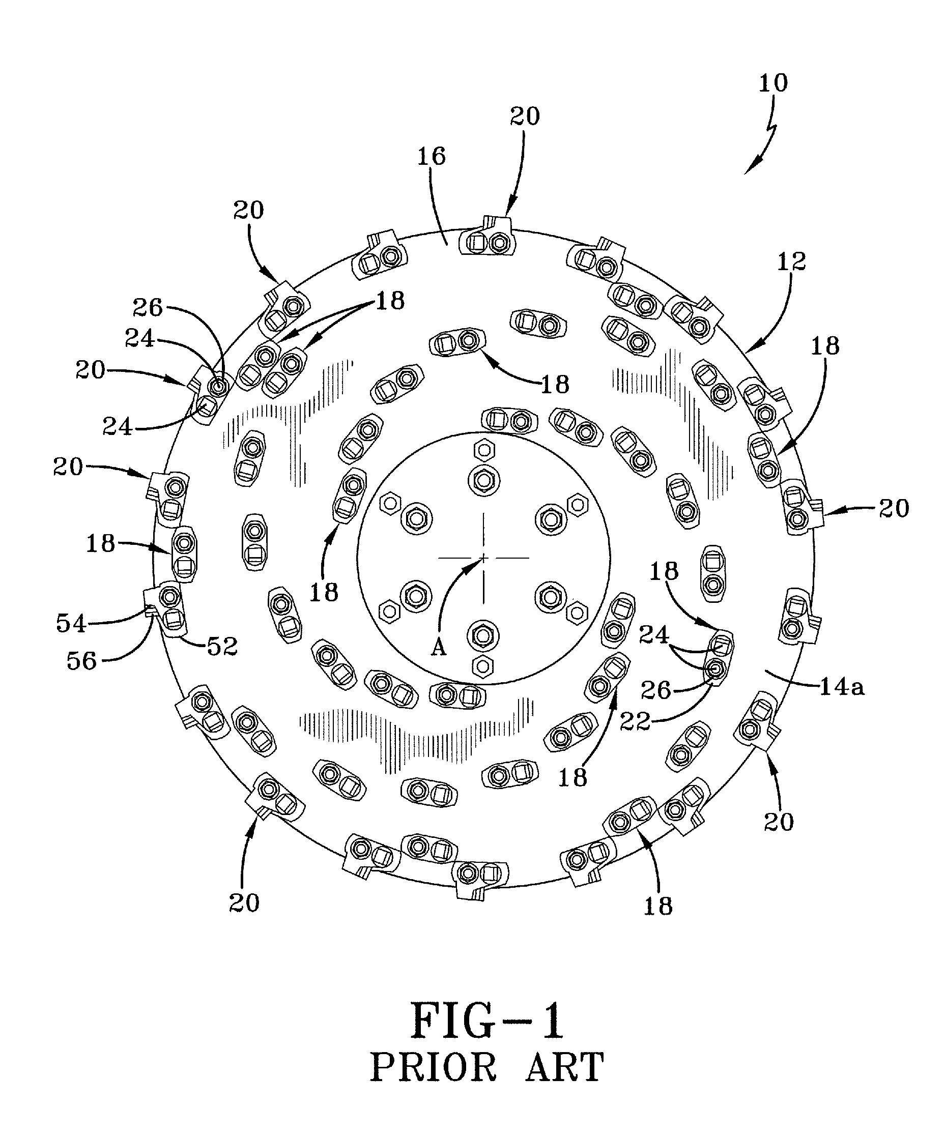
While the prior art helical mounting patterns of the circumferentially-extending side cutter assemblies create an excellent cutting pattern, they leave large areas of the periphery of the wheel unprotected, and thus vulnerable to such extreme wear.
This wear undesirably shortens the life of the wheel.
A second disadvantage of prior art stump grinding wheels is the congested location of certain side cutter assembly pockets with respect to other side cutter assembly pockets and to the peripheral cutter assembly pockets.
Some side cutter assemblies may be mounted in close proximity to one another, and such close proximity of circumferentially-oriented assemblies may cause them to interfere with one another and create congested areas.
In addition, certain side cutter assemblies are mounted along the periphery of the wheel between the peripheral cutter assemblies in a circumferentially-oriented manner, and the close proximity of the side cutter assemblies with the peripheral cutter assemblies may cause them to interfere with the welds that secure the peripheral cutter assemblies to the wheel, thereby creating additional congested areas.
These congested areas may pack with dirt and pieces of the stump, which may in turn cause the wheel to undesirably become unbalanced.
An unbalanced wheel often generates severe vibration and thus requires replacement, resulting in increased cost and lost production.
A third disadvantage of prior art stump grinding wheels is misalignment of the cutting teeth, which may be created by mounting side cutter assemblies in a circumferentially-oriented manner.
More particularly, with prior art stump grinding wheels, the cutting edges of the teeth on one side of a wheel typically are properly aligned to cut a stump, but the teeth on the opposite side of the wheel may not be properly aligned.
The circumferential mounting orientation of the side cutter assemblies often impedes uniform alignment of the cutting edges of the teeth, so that the cutting edges on one side of the wheel are undesirably disposed at different angles when compared to the cutting edges on the other side of the wheel.
However, when the operator advances the wheel into the stump from the opposite direction, which uses the cutting edges on the other side of the wheel that are not properly aligned, the wheel may bounce, vibrate and / or cut poorly.
Such bouncing and vibration can cause damage to the stump grinding machine and lost production.
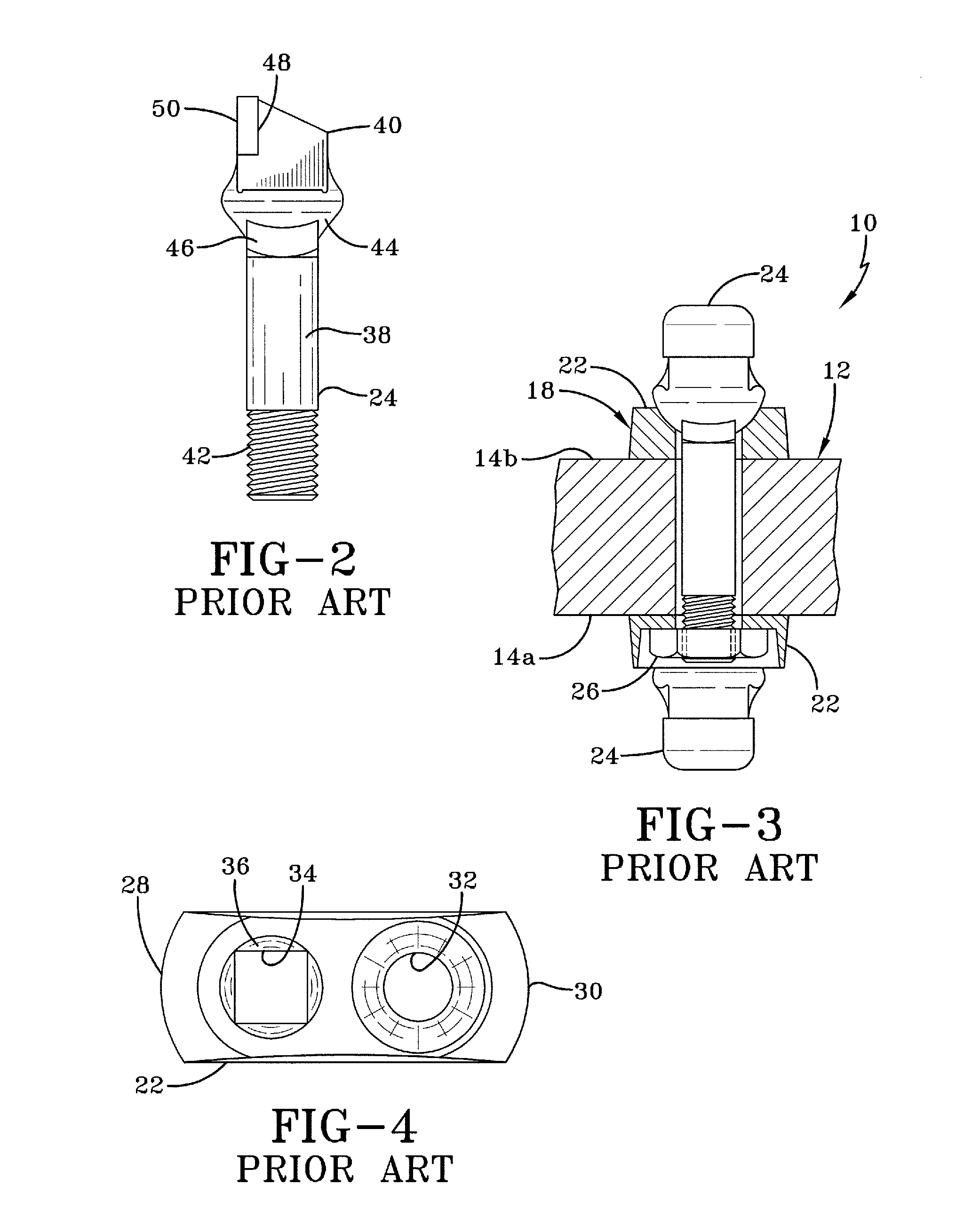
A fourth disadvantage of prior art stump grinding wheels is shifting of the alignment of the teeth when they are tightened down.
Such slight turning of the tooth in the pocket may cause the cutting edge of the tooth to undesirably turn, resulting in the cutting edges of the teeth on one side of the wheel being at different angles from the cutting edges of the teeth on the other side of the wheel, as measured radially from the center of the wheel.
This contributes to the above-described problem of the cutting edges of the teeth cutting well when the operator advances the wheel into the stump one way, but then cutting poorly when the operator advances the wheel into the stump from the opposite direction.
A fifth disadvantage of stump grinding wheels of the prior art is that, while the combination of side cutter assemblies and peripheral cutter assemblies on a wheel works well on large powerful machines, such an aggressive combination of cutter assemblies may cause the wheel to hang up or stall on smaller machines.
More particularly, the use of side cutter assemblies and peripheral cutter assemblies, which grab and dig into the stump as they cut, requires a significant amount of power in order to keep the wheel rotating.
Since smaller stump grinding machines generate less power than larger machines, the smaller machines may not have enough power to keep the wheel moving as the aggressive combination of side cutter and peripheral cutter assemblies grabs and digs into the stump.
In addition, sometimes a wheel having an aggressive combination of side cutter assemblies and peripheral cutter assemblies will move up or climb up on the stump that is being cut, which can upset or overturn a smaller stump grinding machine, potentially damaging the machine.

Method used


Image

  • Stump grinding wheel
  • Stump grinding wheel
  • Stump grinding wheel

Examples


Embodiment Construction

[0043]In order to better understand the stump grinding wheel of the present invention, prior art stump grinding wheels and components of the wheels are shown in FIGS. 1-6. With reference now to FIG. 1, a first prior art stump grinding wheel is indicated generally at 10 and is adapted to be bolted to a rotary drive mechanism of a stump grinding machine (not shown) for rotation about a center axis of rotation A. First prior art stump grinding wheel 10 includes a wheel disc 12. Wheel disc 12 includes a pair of opposing side surfaces 14a, 14b (FIG. 3) and a cylindrical outer peripheral surface or periphery 16, which interconnects the side surfaces. Mounted on wheel disc 12 are side cutter assemblies 18 and first prior art peripheral cutter assemblies 20.

[0044]More particularly, each side cutter assembly 18 is mounted to wheel disc 12 in a generally circumferentially-extending orientation, and the side cutter assemblies form a plurality of generally helical patterns. With additional refe...


PUM


Abstract

A stump grinding wheel includes a wheel disc, which includes multiple recesses formed about its periphery. A peripheral cutter assembly is disposed in each one of the recesses and is mounted on the wheel disc. Multiple side cutter assemblies are mounted on the wheel disc, and each one includes a first pocket and a second pocket. The first pocket is disposed on one side of the wheel disc and the second pocket is disposed on the other side of the wheel disc, and a wear pad is formed adjacent a selected end of each pocket. A cutting tooth is received in aligned openings formed in the first pocket, the wheel disc, and the second pocket. A nut threadably engages the cutting tooth of the side cutter assembly to secure the tooth to the first and second pockets, and to secure the pockets to the wheel disc.

Description

CROSS-REFERENCE TO RELATED APPLICATION[0001]This application claims the benefit of U.S. Provisional Patent Application Ser. No. 60 / 909,760, which was filed on Apr. 3, 2007.BACKGROUND OF THE INVENTION[0002]1. Technical Field[0003]The present invention relates to the art of grinding tree stumps and other materials. More particularly, the invention relates to the art of wheels that are used to grind tree stumps and other materials. Still more particularly, the invention relates to wheels for grinding tree stumps and other materials that provide improved installation, positioning and orientation of cutting tools which are mounted on the wheel, thereby improving the performance and the life of the wheels.[0004]2. Background Art[0005]In order to remove tree stumps and other similar materials from the ground during construction or other work, a stump grinder is typically used. The stump grinder usually includes a driven wheel, which is known as a stump grinding wheel, and specialized cutti...

Claims


Application Information

Patent Timeline
Patent Type & Authority Patents(United States)
IPC IPC(8): B27C1/00A01G23/06
CPCA01G23/067
Inventor PAUMIER, JAMES J.
Owner NEW RIVER EQUIP
Why Eureka
Try Eureka