Acetabular shell removal tool

a technology for removing tools and acetabular shells, which is applied in the field of acetabular shell removal tools, can solve the problems of difficult to keep the chisel precisely at the periphery, damage to the mechanism which holds the liner in place, and the acetabular shell of the prosthesis will become completely embedded in the surrounding bone and need to be cut fr

Active Publication Date: 2010-06-29
STEVEN M TEENY M D
View PDF29 Cites 76 Cited by
  • Summary
  • Abstract
  • Description
  • Claims
  • Application Information

AI Technical Summary

Problems solved by technology

A difficulty in doing this is that the acetabular shell of the prosthesis will become completely embedded in the surrounding bone and needs to be cut free.
A problem with this process is that it is difficult to keep the chisel precisely at the periphery of the acetabular shell and often excess bone is removed with the shell.
These screws need to be removed before the shell can be removed and doing this requires that the polyethylene liner be removed from the shell, which often damages the mechanism which holds the liner in place.

Method used


Image

  • Acetabular shell removal tool
  • Acetabular shell removal tool
  • Acetabular shell removal tool

Examples


first embodiment

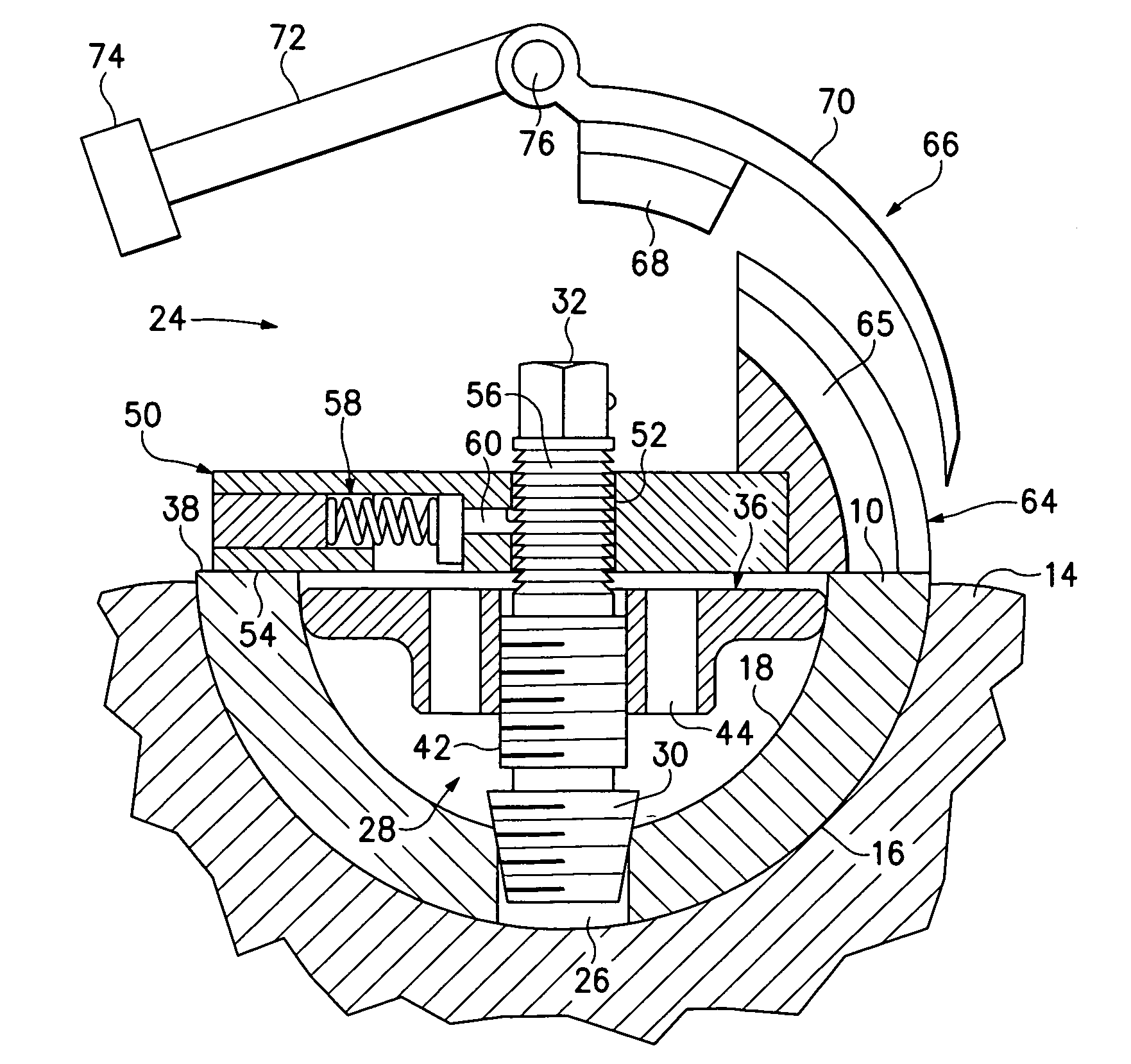
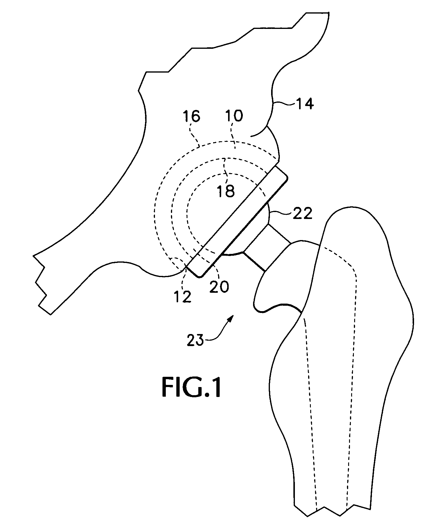
[0015]The tool of the subject invention facilitates the removal of the shell. Referring to FIGS. 2-9 of the drawings, the tool 24 is utilized where the shell has an opening 26 at its center which was used to instill the shell. The tool 24 includes an anchor 28, FIG. 2, which attaches to the shell. Located at the inner end of the anchor 28 is a seat 30. The seat 30 can either have self-tapping threads or threads that mate with the existing threads in the opening 26. A hex head 32 is located at the outer end of the anchor so that a wrench 34 can be attached to the anchor to screw the seat 30 into the opening 26.

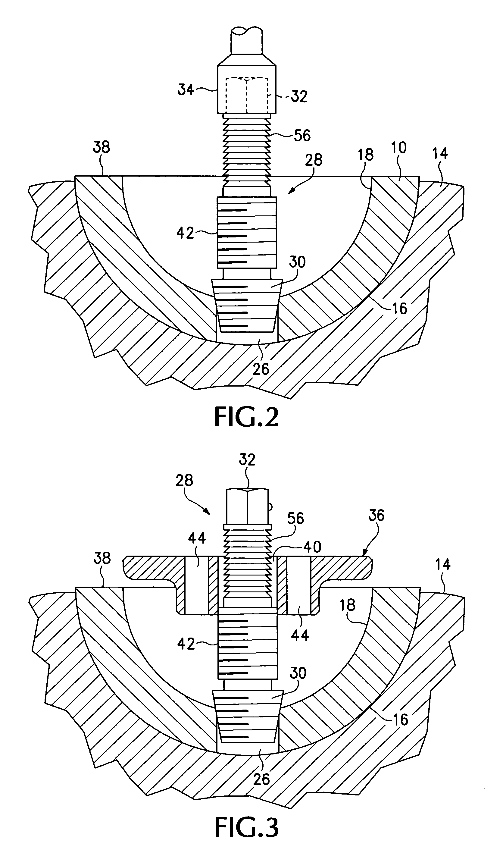
[0016]Referring now also to FIGS. 3 and 4, once the anchor is in place a centering plate 36 is installed on it. The centering plate 36 is circular in cross-section and has a diameter which causes it to contact the inner surface 18 of the shell slightly below its outer edge 38. Located in the center of the centering plate 36 is a hole 40. The hole 40 and the center portion 42 of...

second embodiment

[0021]Referring now to FIGS. 10-12, when the acetabular shell 10 does not have an opening in it, the tool 78 is used. In this embodiment the tool is attached to the shell 10 through an annular slot 80 which is located in the upper portion of the inner surface 18 of the shell to hold the polyethylene liner 20 into the shell. The tool 78 includes a clamping ring 82 having an outer diameter which is slightly less than the diameter of the inner surface of the shell at the location of the slot 80. The clamping ring 82 has three spring-loaded detents 84 having teeth 85 that project from the periphery of the clamping ring and snap into the slot 80 when the clamping ring is pushed into the shell. The detents 84 are similar to the detents 58. The clamping ring has a planer top surface 88 which is located below the upper edge 38 of the shell when the clamping ring 82 is inserted into the shell and the teeth 85 are seated in the slot 80. Located in the center of the clamping ring 82 is a threa...


PUM


Abstract

A tool for separating an acetabular shell of a hip prosthesis from the surrounding pelvic bone includes a fixture which attaches to the acetabular shell and has a chisel guide mounted on it. A chisel associated with the chisel guide is curved to conform to the outer periphery of the acetabular shell, and the chisel guide causes the chisel to circumscribe the acetabular shell as the chisel is inserted between the acetabular shell and the pelvis.

Description

BACKGROUND OF THE INVENTION[0001]Total hip anthroplasty has become a relatively common procedure. It also is becoming more common to replace the prosthesis after a period of time. A difficulty in doing this is that the acetabular shell of the prosthesis will become completely embedded in the surrounding bone and needs to be cut free. The traditional method of accomplishing this has been to use hand-held, curved chisels and a mallet to cut and pry the acetabular shell away from the bone. A problem with this process is that it is difficult to keep the chisel precisely at the periphery of the acetabular shell and often excess bone is removed with the shell.[0002]The X-PLANT acetabular shell removal tool sold by the Zimmer Company reduces this problem to some degree. The X-PLANT removal tool provides a curved chisel having the same contour as the outer periphery of the acetabular shell. The chisel is attached to a shaft having a ball at its extremity which is sized to be inserted into t...

Claims


Application Information

Patent Timeline
Patent Type & Authority Patents(United States)
IPC IPC(8): A61F2/00
CPCA61F2/4609A61F2002/30387A61F2002/30471A61F2002/30492A61F2220/0091A61F2002/3054A61F2002/4619A61F2002/4629A61F2220/0025A61F2002/30505
Inventor TEENY, STEVEN M.JACOBSEN, STEVEN G.
Owner STEVEN M TEENY M D
Why Eureka
Try Eureka