Image forming apparatus

a technology of forming apparatus and forming plate, which is applied in the direction of thin material handling, article separation, article delivery, etc., can solve the problems of sheet pb>0/b> jamming, and achieve the effect of smooth switching back conveyan

Active Publication Date: 2010-07-06
KYOCERA DOCUMENT SOLUTIONS INC
View PDF6 Cites 10 Cited by
  • Summary
  • Abstract
  • Description
  • Claims
  • Application Information

AI Technical Summary

Benefits of technology

[0007]An object of the present invention is to prevent hanging of a sheet so as to smoothly perform a switch-back conveyance.

Problems solved by technology

However, at the time of switching back, there has been a problem that the leading end of the sheet P0 hangs down and is oriented toward the main conveying passage 100B, not the conveying passage 100D, so that the sheet P0 reversely moves to the discharging section 104, and the sheet P0 jammed.

Method used


Image

  • Image forming apparatus
  • Image forming apparatus
  • Image forming apparatus

Examples


first embodiment

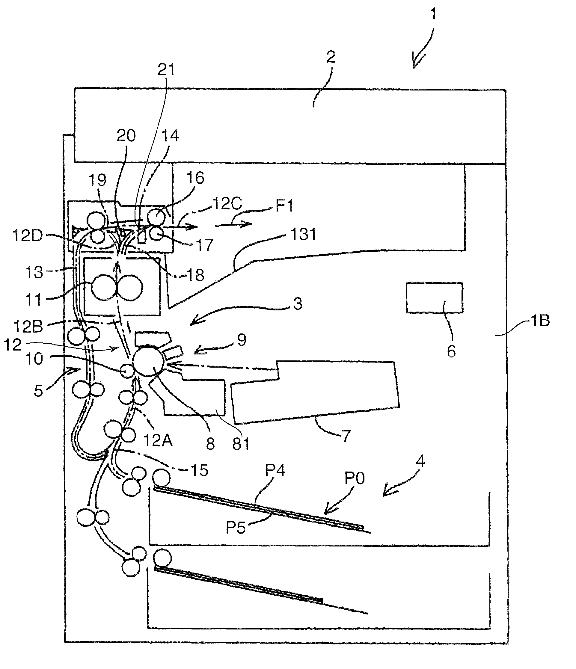
[0020]FIG. 1 is a front sectional view showing a schematic configuration of an image forming apparatus 1 in accordance with an embodiment of the present invention. The image forming apparatus 1 includes an apparatus main body 1B and a reading section 2 which is arranged on top of the apparatus main body 1B and optically reads a document image to be copied.

[0021]The apparatus main body 1B accommodates an image forming section 3 for forming an image onto a sheet P0 in accordance with image data of a document image which is obtained from the reading section 2, a sheet-supplying section 4 for supplying a sheet P0 to the image forming section 3, a sheet-conveying section 5 for conveying the sheet P0 to outside from the sheet-supplying section 4 through the image forming section 3, and a controller 6 that executes controlling operations of the above-described sections of the image forming apparatus 1. Between the reading section 2 and the apparatus main body 1B, there is provided a sheet-...

second embodiment

[0048]FIG. 5 is a sectional view of the peripheral portion of the sheet-discharging rollers 16 and 17 in accordance with a second embodiment of the present invention. FIG. 6 is a perspective view of the sheet-discharging rollers 16 and 17 viewed from the sheet-discharging side. FIG. 7 is an enlarged view showing a left side end portion of FIG. 6. In these drawings, portions which are the same as those shown in FIGS. 1-4 are identified by the same reference signs, and description regarding these parts will be omitted or simplified.

[0049]In the second embodiment, an example is shown in which second flexible members 25 are arranged on a downstream side of the sheet-discharging rollers 16 and 17 in the sheet convey direction (forward conveyance). The second flexible members 25 orients the widthwise opposite end portions of the sheet P0 toward a central portion by contacting with opposite end portions of the sheet P0 which is discharged from the sheet-discharging rollers 16 and 17 toward...

third embodiment

[0056]FIG. 8 is a sectional view of the peripheral portion of the sheet-discharging rollers 16 and 17 in accordance with a third embodiment of the present invention. In the third embodiment, the first flexible members 21 in accordance with the first embodiment and the second flexible members 25 in accordance with the second embodiment are provided.

[0057]Configurations, arrangements, and functions of the first flexible members 21 and the second flexible members 25 are the same as those described above. The first flexible members 21 are arranged on the upstream side of the sheet-discharging rollers 16 and 17. When the sheet P0 is switched back, the first flexible members 21 come in contact with the underside surface of the sheet P0 to allow the sheet P0 to move to the inlet portion 19 of the reversing conveying passage 13 in a substantially horizontal posture. The second flexible members 25 are arranged on the downstream of the sheet-discharging rollers 16 and 17, and come in contact ...


PUM

PropertyMeasurementUnit
flexibleaaaaaaaaaa
flexibilityaaaaaaaaaa
sheet-conveying directionaaaaaaaaaa

Abstract

An image forming apparatus includes a first sheet conveying passage that conveys a sheet through an image forming section. A sheet-discharging roller is on an outlet side of the first sheet conveying passage and can rotate in opposite directions. A second sheet conveying passage has an inlet connected to the first sheet conveying passage downstream from the image forming section and an outlet connected to the first sheet conveying passage upstream from the image forming section. A controller controls double-sided printing by causing the sheet-discharging roller to rotate forward to advance the sheet outside the sheet-discharging roller, and then to rotate in reverse to execute a switchback for transporting the sheet to the inlet side of the second sheet conveying passage and then to return the sheet to the upstream of the image forming section. An assisting mechanism adjusts a posture of the sheet to assist the switchback.

Description

BACKGROUND OF THE INVENTION[0001]1. Field of the Invention[0002]The present invention relates to an image forming apparatus capable of forming images on opposite sides of a sheet.[0003]2. Description of the Related Art[0004]An image forming apparatus which has a function of performing image forming on opposite sides of a sheet has been widely used. In such a double-sided image forming process of the apparatus, an image is formed on a front side of a sheet, and then image forming on a back side of the sheet is conducted upon reversing back the sheet by a switch back conveyance so that the sheet is reversed back to an image forming section.[0005]The double-sided image forming will be specifically described with reference to FIG. 9. Firstly, a sheet P0 which is accommodated in a sheet-feeding cassette 101 is conveyed to a transferring section 102 through a main conveying passage 100A on an upstream. Then, an image forming processing is applied to a front side of the sheet P0. After tha...

Claims


Application Information

Patent Timeline
Patent Type & Authority Patents(United States)
IPC IPC(8): B65H39/10
CPCB65H5/36B65H29/14B65H29/70B65H2301/33312B65H2404/56B65H2404/61B65H2801/06B65H2220/09
Inventor KAWASHIMA, TETSURO
Owner KYOCERA DOCUMENT SOLUTIONS INC
Why Eureka
Try Eureka