
Drive device for a movably mounted furniture part

a technology for moving parts and drives, which is applied in the direction of furniture parts, household applications, and variable dimension cabinets, etc., can solve problems such as energy storage devices, and achieve the effect of smooth pulling ou

Active Publication Date: 2010-07-06
JULIUS BLUM GMBH
View PDF20 Cites 12 Cited by
  • Summary
  • Abstract
  • Description
  • Claims
  • Application Information

AI Technical Summary

Benefits of technology

[0008]The opening of the drawer into the fully open position by the inventive drive device is advantageous in several ways. With the opening of short drawers, rebounding can be effectively prevented, particularly if there is damping over the last region of opening of the pull-out path. Another advantage is the ease of operation and the avoidance of accidental self-closure. If removably fitted inserts, or objects, are inside the drawer, which require the drawer to be pulled out fully in order for them to be removed, the drive device according to the invention can be used to advantage in such a situation.
[0009]A preferred embodiment of the invention provides that the energy storage device has a spring device with at least one spring. As a result, the drive device is simple in its construction and is inexpensive to make. Alternatively, or as an additional measure, the energy storage device can also be equipped with at least one pressurized gas storage device. In this case, it can also be advantageous to use the power from an external energy source—e.g. an electric motor—to form and / or assist the energy storage device.
[0012]An advantageous embodiment of the invention results if the rocker segment is preferably guided in a displaceable manner linearly along a guide path. The rocker segment can be guided with accuracy along the path of movement provided for it, thus permitting reliable coupling which is free of clearance. The guide path can lie in a rail which is held by a fixing means to the side wall of the furniture body.
[0014]So that the movable furniture part is not brought into the fully open position with too much momentum, it is advantageously provided that a damping device is provided which dampens the movement of the furniture part over at least part of its path of opening. The damping device can essentially be based on any solutions known in the prior art, the use of linear dampers, or even rotary dampers, advantageously being possible.
[0016]Another advantageous embodiment of the invention results if a closure device is additionally provided by means of which the movable furniture part can be moved into its fully closed position. The movable furniture part can thus be moved within the region of the two end positions of the path of movement, both into the fully closed position as well as into the fully open position, gentle and smooth closure and opening operations being possible into both end positions.

Problems solved by technology

During the closure operation of the movable furniture part, the energy storage device is rechargeable, and the energy storage device is only effective over part of the path of movement of the furniture part.

Method used


Image

  • Drive device for a movably mounted furniture part
  • Drive device for a movably mounted furniture part
  • Drive device for a movably mounted furniture part

Examples


Embodiment Construction

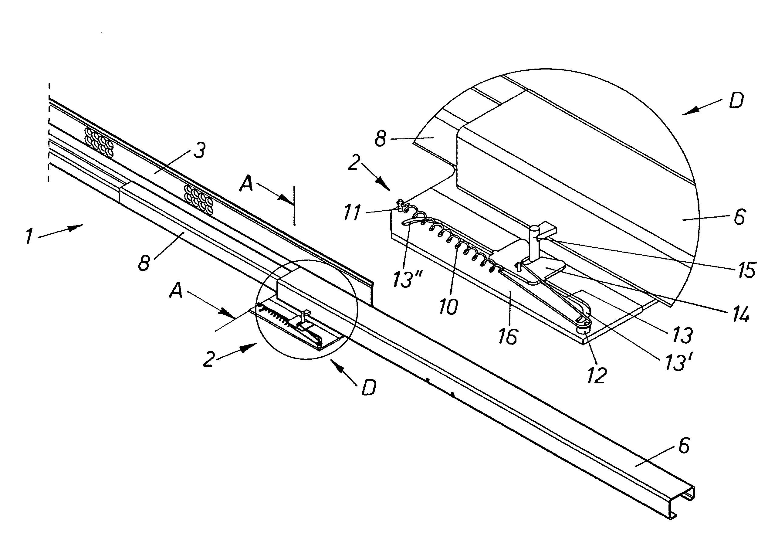
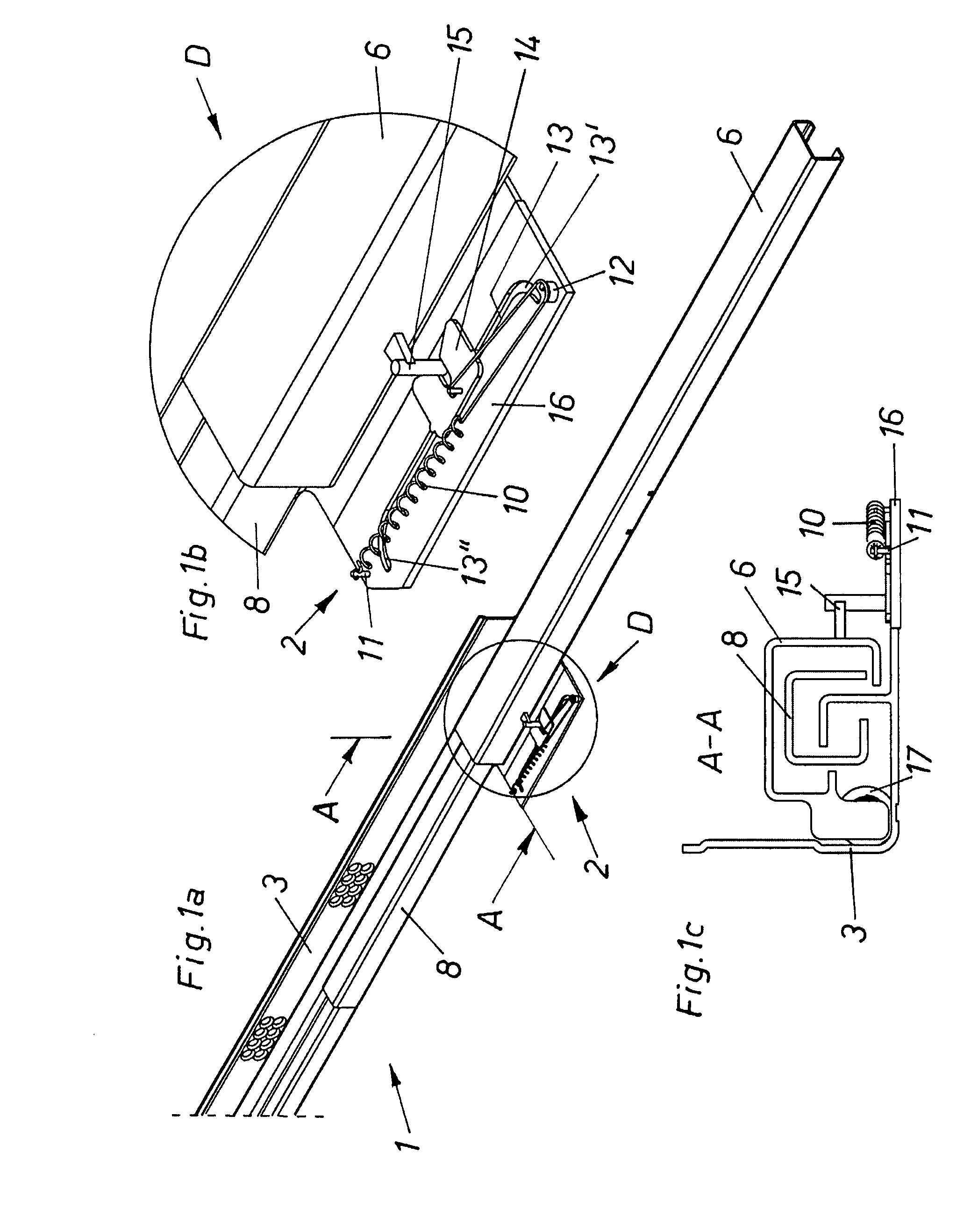
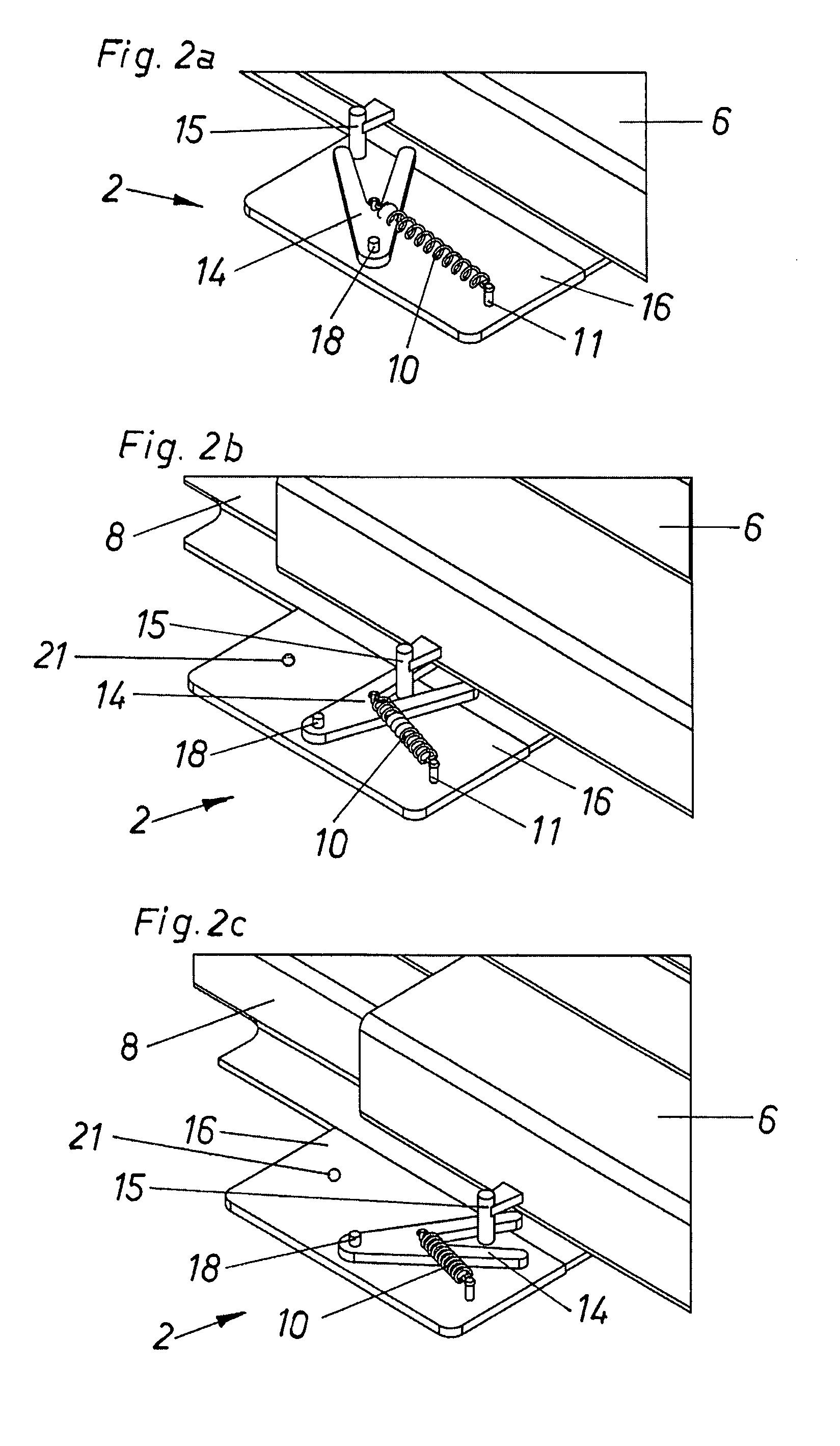
[0026]FIG. 1a shows the front region of a pull-out guide fitting 1 for drawers with the drive device 2 according to the invention. FIG. 1b is a view of the detail D in FIG. 1a, and FIG. 1c is a sectional drawing taken along the line A-A of FIG. 1a. The pull-out guide fitting 1 is in the open position, the drawer rail 6 being engaged with the drive device 2. Other than in respect of the drive device 2, the pull-out guide fitting 1 corresponds to the prior art, i.e. a carcass rail 3 is fixedly connected with a furniture body. Between the carcass rail 3 and the drawer rail 6 there is a central rail 8 which is displaceable relative to these two rails 3, 6. The load between the rails is transmitted by means of rollers, balls or rolls, or conventional carriages, not shown. The drive device 2 is preferably disposed in the front half of the pull-out path of a drawer which is fixedly connected to the drawer rail 6. The drive device 2 can be arranged between the side wall of the drawer and th...


PUM


Abstract

The invention relates to a drive device for a furniture part that is displaceably mounted in relation to a furniture body, in particular for a drawer or similar. The device includes an energy accumulator device, which supports the displacement of the furniture part. According to the invention, the displaceable furniture part can be essentially displaced into a fully open position by the energy accumulator device, thus partially discharging the energy accumulator device. The energy accumulator device is then re-charged during the closing operation of the displaceable furniture part. The energy accumulator device only acts on part of the displacement path of the furniture part.

Description

[0001]This application is a continuation of International Application No. PCT / AT2005 / 000448, filed Nov. 10, 2005.BACKGROUND OF THE INVENTION[0002]The present invention relates to a drive device for a furniture part which is mounted movably relative to a furniture body, particularly for a drawer or the like, having an energy storage device which assists the movement of the furniture part.[0003]The invention also relates to an item of furniture with a furniture part which is mounted movably relative to a furniture body, and also to a method of moving a furniture part of this kind into its open position.[0004]According to the prior art, numerous embodiments of retraction devices are known, in which an energy storage device conveys the furniture part into the fully closed position. It is also known to provide such retraction devices with damping devices, which, if the movable furniture part is swung shut, at least reduce the banging noises occurring thereby, and thus also reduce the mec...

Claims


Application Information

Patent Timeline
Patent Type & Authority Patents(United States)
IPC IPC(8): A47B88/04
CPCA47B88/047A47B88/0477A47B88/467A47B88/463
Inventor KLEINSASSER, GERHARD
Owner JULIUS BLUM GMBH
Learn More