Positive locking light fixture with faceplate

a technology of faceplate and light fixture, which is applied in the direction of lighting support devices, coupling device connections, lighting and heating apparatuses, etc. it can solve the problems of shock and vibration, faceplate loosening, falling, and presenting several drawbacks, and achieves the effect of low cost manufacturing

Inactive Publication Date: 2010-07-06
INTEGRATED ILLUNINATION SYST
View PDF8 Cites 62 Cited by
  • Summary
  • Abstract
  • Description
  • Claims
  • Application Information

AI Technical Summary

Benefits of technology

[0012]In a further embodiment of the invention, the faceplate, as noted above, does not have a window (i.e. glass or similar transparent member) and the window is connected to the housing of light fixture, such that when the faceplate is removed, the window remains in place on the fixture. The glass in this embodiment can be retained via mechanical or adhesive retention depending on the application. Apart from reducing the weight of the faceplate, this feature also permits the ready interchange of one faceplate with another.
[0022]While most any method of manufacturing from a variety of materials may be used, the present invention light fixture lends itself well to stamping, thus allowing the entire light fixture housing to be manufactured from a single sheet of metal, thus promoting low cost manufacturing.

Problems solved by technology

While this mounting system may prove effective for installations under normal conditions, it presents several drawback when used in installations where shock and vibration are prevalent, such as marine applications (including commercial and recreational marine vessels of all sizes and marine platforms).
Shock and vibration will eventually loosen up the faceplate such that it slides down the ramp and falls.
This presents several problems.
If the faceplate does in fact fall from the fixture due to heavy shock and or vibration, there is the risk that of injury to the vessel operator and / or passengers.
This will cause harm, distraction, and / or potential burns particularly when the faceplates are used on halogen based fixtures and can heat up to several hundred degrees.
A further problem resides in that often a red filter will be added to the glass for night operation.
Should the faceplate and filter fall from the fixture, the vessel operator may potentially be blinded from the bright white light from the filter-less fixture.

Method used


Image

  • Positive locking light fixture with faceplate
  • Positive locking light fixture with faceplate
  • Positive locking light fixture with faceplate

Examples


first embodiment

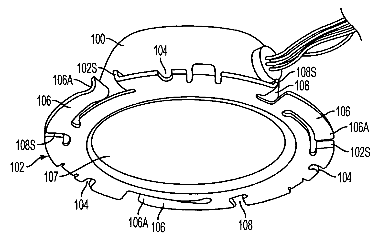
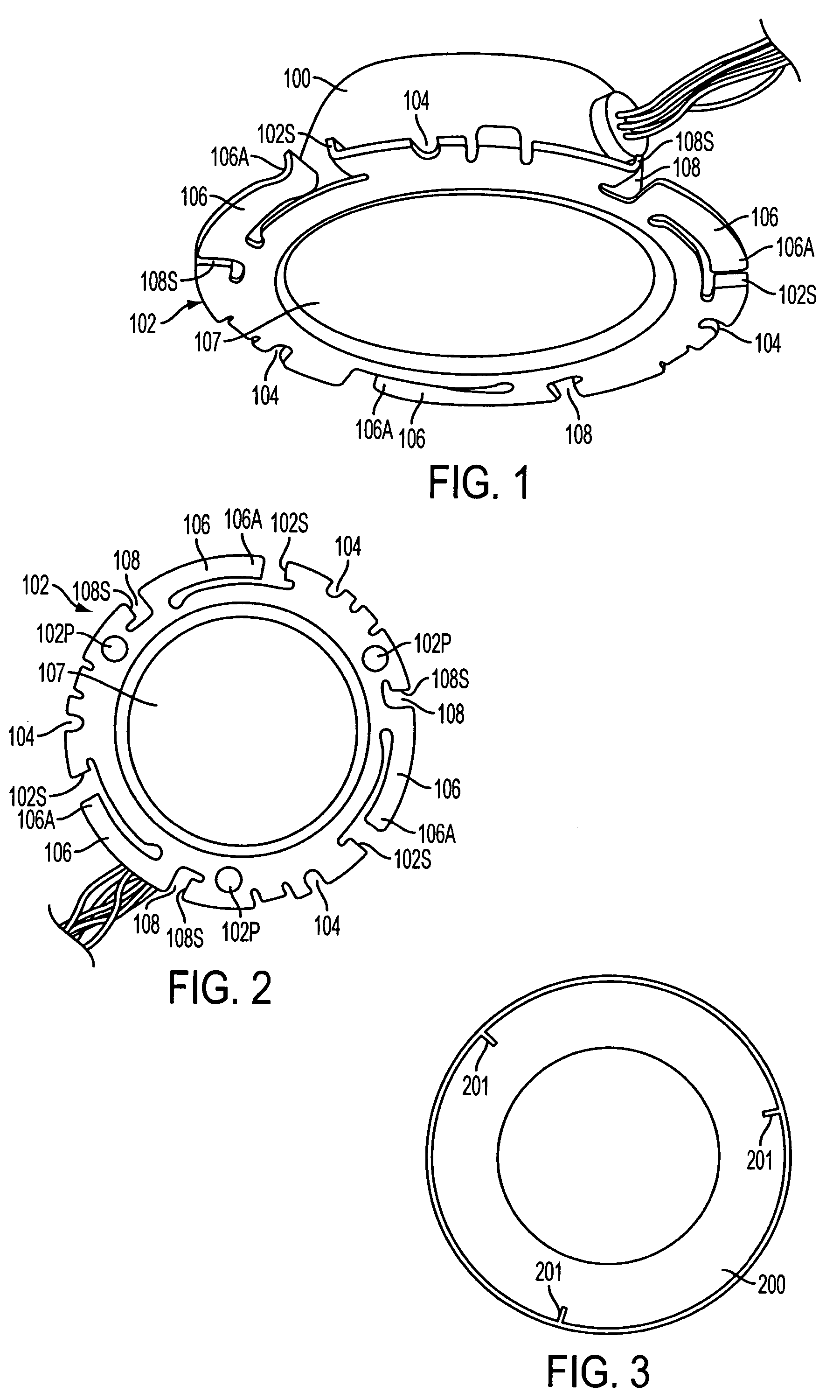
[0032]Referring to FIGS. 1 and 2, in a first embodiment, a housing 100 is formed with an annular flange or rim 102. This rim or flange 102 is apertured so that a plurality of mounting openings 104 which facilitate the connecting of the housing to a panel such as a ceiling or overhead structure 101, are formed at predetermined intervals. A plurality, in this case three, resilient arms 106 are also defined. Each of these arms 106 are arcuately curved in the manner best appreciated from FIG. 2, and are formed with hook features 106A at the free ends thereof. These hook features 106A function as detent recesses as will become apparent hereinlater. Each arm 106 is bent so as to be angled upwardly slightly with respect to the plane of the annular rim 102 to produce a bias against which they can be flexed.

[0033]A window 107 of light transparent material is disposed in the mouth of the housing 100 to close off the interior and protect a light source, camera or the like which is disposed the...

second embodiment

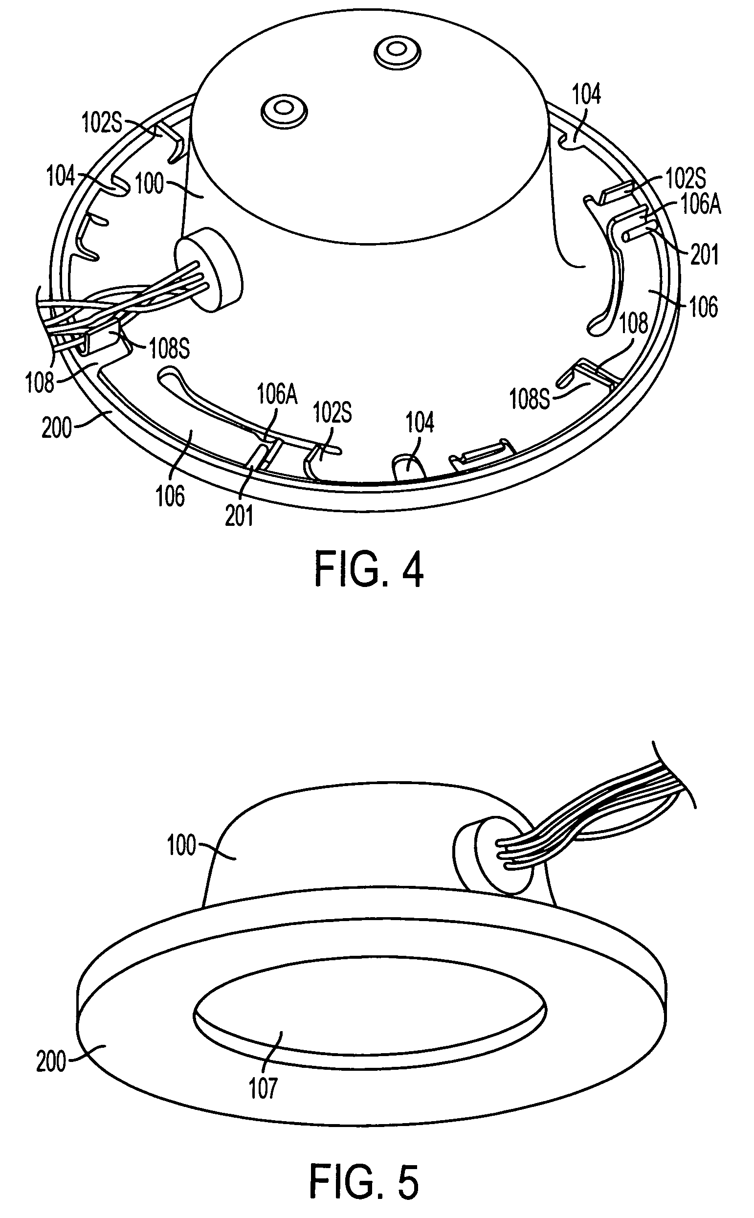
[0040]FIG. 7 illustrates the invention. In this embodiment, a window is connected to and forms part of the faceplate 200. This embodiment facilitates easy access to the interior of the housing for maintenance or the like. By providing an elastomeric gasket about the outer peripheral edge of the faceplate, sealing between the faceplate and housing can be achieved.

[0041]In FIG. 7 a light source 1001 is schematically depicted within the housing 100. This light source can take the form of an LED (Light Emitting Diodes) lighting arrangement which is configured to produce white light or a plurality of different colors which can be mixed to produce different colors including white light.

[0042]It will be readily seen by one of ordinary skill in the art that embodiments according to the present invention fulfill many of the advantages set forth above. After reading the foregoing specification, one of ordinary skill will be able to affect various changes, substitutions of equivalents and vari...


PUM


Abstract

An assembly has a faceplate having inwardly extending pins and a housing having holes for receiving said inwardly extending pins. Vibration resistant means is provided for locking the faceplate to the housing.

Description

RELATED APPLICATIONS[0001]The present invention claims priority from Provisional Application No. 60 / 721,998, filed Sep. 30, 2005, entitled POSITIVE LOCKING LIGHT FIXTURE WITH FACEPLATE, the disclosure of which is hereby incorporated by reference in its entirety.BACKGROUND OF THE INVENTION[0002]1. Field of the Invention[0003]The present invention relates generally to light fixtures and more specifically to light fixtures or assemblies wherein selectively removable features / elements are resistant to loosening / disconnection under the influence of vibration such as occurs in vehicles / vessels or vibration prone environments.[0004]2. Description of the Related Art[0005]To date, there are light fixtures available that that use a removable faceplate as a means of concealing fixture housing mounting screws. These faceplates typically include a decorated trim ring (i.e. painted or plated) and a glass window installed to the trim ring.[0006]The faceplates typically mount by twisting the facepl...

Claims


Application Information

Patent Timeline
Patent Type & Authority Patents(United States)
IPC IPC(8): H01R33/00
CPCB60Q3/0203B63B45/06F21S8/02F21V3/00F21V17/14F21V15/04F21Y2101/02Y10S362/80F21Y2115/10B60Q3/51
Inventor ZAMPINI, II, THOMASZAMPINI, THOMAS L.ZAMPINI, MARK A.
Owner INTEGRATED ILLUNINATION SYST
Why Eureka
Try Eureka