Blood pump apparatus

a technology of pumping apparatus and pump head, which is applied in the direction of piston pump, positive displacement liquid engine, prosthesis, etc., can solve the problems of inability to find the position of the impeller and inability to check whether the impeller is rotating

Inactive Publication Date: 2010-07-06
TC1 LLC
View PDF32 Cites 60 Cited by
  • Summary
  • Abstract
  • Description
  • Claims
  • Application Information

AI Technical Summary

Problems solved by technology

However, in the pump apparatus disclosed in the patent document 1, it is impossible to find the position of the impeller.
Thus it is impossible to check whether the impeller is rotating without contacting the inner surface of the housing with a predetermined interval kept between the impeller and the inner surface of the housing.

Method used


Image

  • Blood pump apparatus
  • Blood pump apparatus
  • Blood pump apparatus

Examples


Embodiment Construction

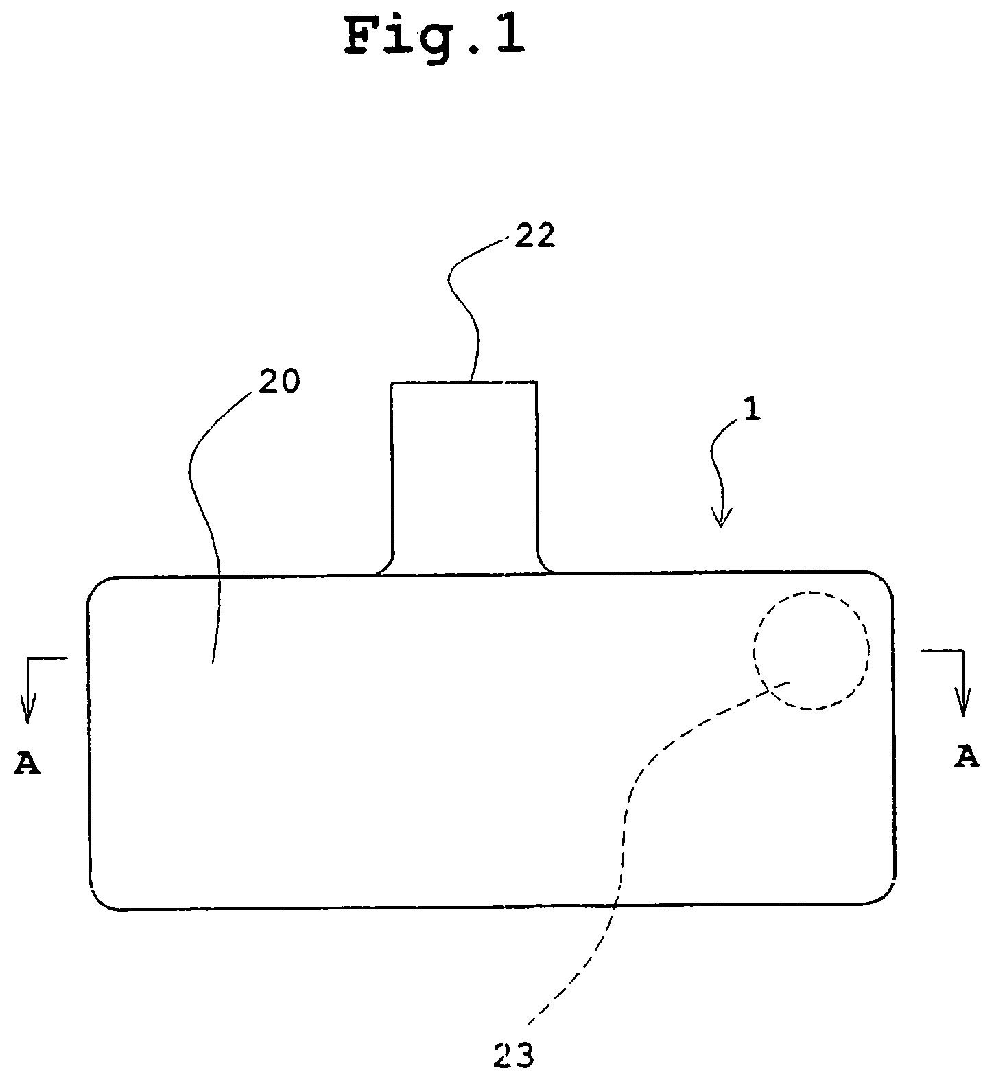
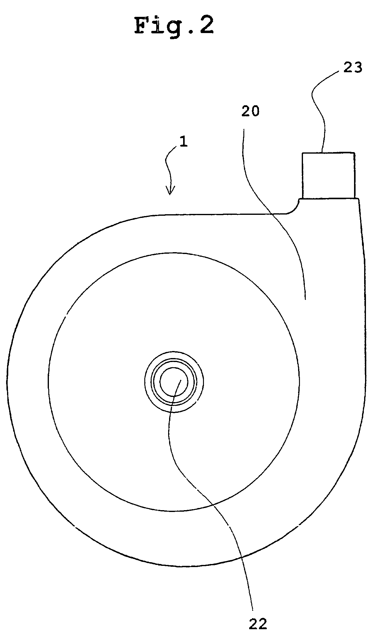
[0045]FIG. 1 is a front view showing a centrifugal blood pump apparatus according to an embodiment of the present invention. FIG. 2 is a plan view showing the centrifugal blood pump apparatus shown in FIG. 1. FIG. 3 is a vertical sectional view showing the centrifugal blood pump apparatus of the embodiment shown in FIG. 1. FIG. 4 is a sectional view, taken along a line A-A in FIG. 1, showing the centrifugal blood pump apparatus. FIG. 5 is a sectional view showing a state in which an impeller is removed from the sectional view, taken along a line A-A in FIG. 1, showing the centrifugal blood pump apparatus.

[0046]A centrifugal blood pump apparatus 1 of the present invention includes a housing 20 having a blood inlet port 22 and a blood outlet port 23; a centrifugal pump section 2 including an impeller 21 having a magnetic material 25 disposed therein and rotating inside the housing 20 to feed a fluid by a centrifugal force generated during its rotation; an impeller rotational torque ge...


PUM


Abstract

A blood pump apparatus comprises a housing, a centrifugal pump section including an impeller and rotating inside the housing to feed a fluid by a centrifugal force, an impeller rotational torque generation section for attracting thereto said impeller and rotating said impeller; and a plurality of grooves for hydrodynamic bearing provided on an inner surface of said housing at a side of said impeller rotational torque generation section, each of the grooves for hydrodynamic bearing having a first side and a second side both extending from a periphery of said portion in which a groove for hydrodynamic bearing is formed toward a central side thereof and opposed to each other, a third side connecting one end of said first side and one end of said second side to each other, and a fourth side connecting said other end of said first side and said other end of said second side to each other; said first side and said second side are formed as a circular arc respectively in such a way that centers of said circular arcs are different from each other.

Description

BACKGROUND OF THE PRESENT INVENTION[0001]In recent medical treatment, centrifugal blood pumps are increasingly used in artificial heart / lung units for extracorporeal blood circulation. Centrifugal pumps of the magnetic coupling type wherein a driving torque from an external motor is transmitted to an impeller through magnetic coupling are commonly used because the physical communication between the blood chamber of the pump and the exterior can be completely excluded and invasion of bacteria can be prevented.[0002]The turbo-type pump disclosed in Japanese Patent Application Laid-Open No. 4-91396 (patent document 1) is described below as an example of the centrifugal blood pump. In the turbo-type pump disclosed therein, the magnetic coupling is formed by the first permanent magnet provided at one side of the impeller and the second permanent magnet opposed to the first permanent magnet through the housing. The rotor on which the second permanent magnet is mounted is rotated. Thereby ...

Claims


Application Information

Patent Timeline
Patent Type & Authority Patents(United States)
IPC IPC(8): F04B17/03F16C32/06A61M1/10F04B17/00F04B35/04F04D15/00F04D29/04F04D29/047
CPCA61M1/101F04D15/0088A61M1/1036F04D13/0666A61M1/1017F04D29/047F04D13/027A61M60/824A61M60/419A61M60/422A61M60/148A61M60/232
Inventor YAEGASHI, MITSUTOSHIASADA, TAKEHIKOMORI, TAKEHISAOZAKI, TAKAYOSHISUZUKI, KENICHI
Owner TC1 LLC
Why Eureka
Try Eureka