Demodulation circuit for use in receiver using if directing sampling scheme
a demodulation circuit and receiver technology, applied in the field of demodulation circuits for use in receivers, can solve the problems of high cost and high power consumption, and achieve the effect of small hardware size and low power consumption
- Summary
- Abstract
- Description
- Claims
- Application Information
AI Technical Summary
Benefits of technology
Problems solved by technology
Method used
Image
Examples
Embodiment Construction
[0029]Certain embodiments of the present invention will be described in greater detail with reference to the accompanying drawings.
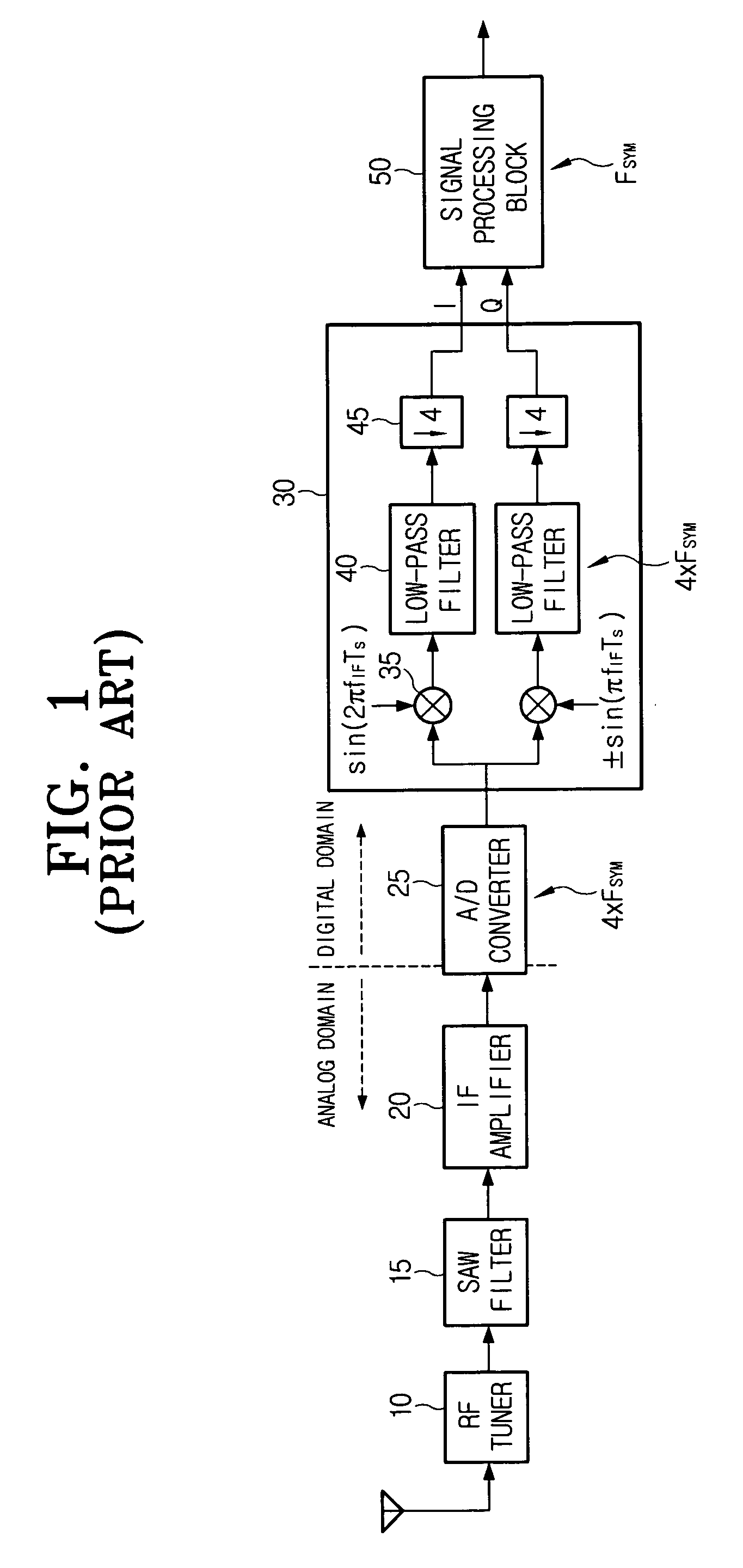
[0030]In a general receiver using an IF direct sampling scheme, an A / D converter simply digitizes an IF signal and provides the digitized IF signal to a demodulation circuit. Meanwhile, an A / D converter in a demodulation circuit in accordance with the present invention not only digitizes an IF signal but also provides a digitized signal in response to a clock signal at a frequency four times a frequency of a baseband signal to a demodulation circuit.
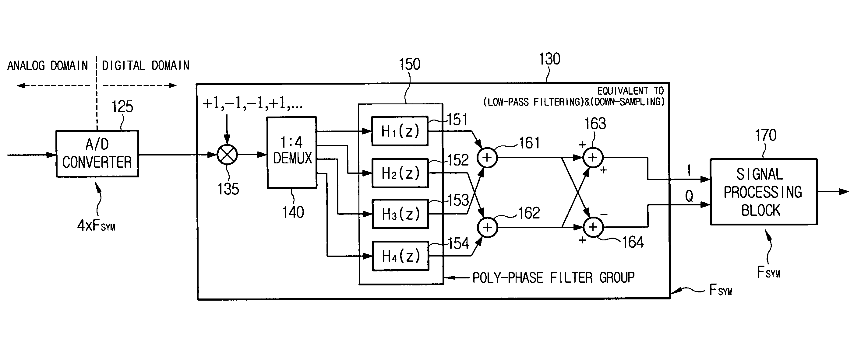
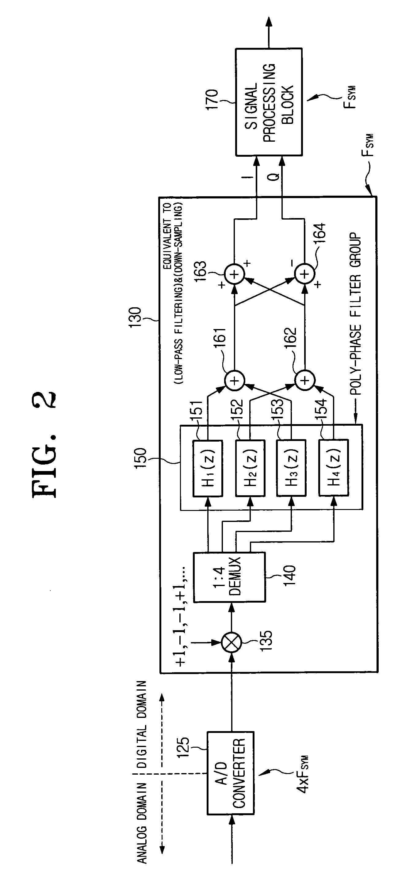
[0031]FIG. 2 illustrates a block diagram of a demodulation circuit for use in a receiver using an IF direct sampling scheme, in accordance with one embodiment of the present invention.
[0032]A demodulation circuit 130 includes a mixer 135, a DEMUX 140, a polyphase filter (PPF) 150, and an LPF comprised of a plurality of adders.
[0033]The mixer 135 receives a coefficient corresponding to the sine values or the c...
PUM
 Abstract
Description
Claims
Application Information
 - R&D
- Intellectual Property
- Life Sciences
- Materials
- Tech Scout
- Unparalleled Data Quality
- Higher Quality Content
- 60% Fewer Hallucinations
Browse by: Latest US Patents, China's latest patents, Technical Efficacy Thesaurus, Application Domain, Technology Topic, Popular Technical Reports.
© 2025 PatSnap. All rights reserved.Legal|Privacy policy|Modern Slavery Act Transparency Statement|Sitemap|About US| Contact US: help@patsnap.com


