Laser display device and optical coupler therefor

a laser display device and optical coupler technology, applied in waveguides, lighting and heating apparatuses, instruments, etc., can solve problems such as speckles, and achieve the effects of reducing speckle noise, clear image, and simplifying the structure of laser display devices

Active Publication Date: 2010-07-06
LG ELECTRONICS INC
View PDF6 Cites 3 Cited by
  • Summary
  • Abstract
  • Description
  • Claims
  • Application Information

AI Technical Summary

Benefits of technology

[0011]One object of the present invention is to provide a laser display device, which eliminates speckles, i.e., an interference fringe of laser light, without affecting the construction of the display device or light transmittance, thus displaying a clear image.
[0012]Another object of the present invention is to provide an optical coupler, which uniformly mixes laser beams while reducing speckle noise generated due to the coherence of the laser beams, and simplifies the structure of a laser display device.

Problems solved by technology

However, when the laser light source is used in display devices, speckles occur due to the coherence of laser beams in that the laser beams have the same special and temporal phases.

Method used


Image

  • Laser display device and optical coupler therefor
  • Laser display device and optical coupler therefor
  • Laser display device and optical coupler therefor

Examples


first embodiment

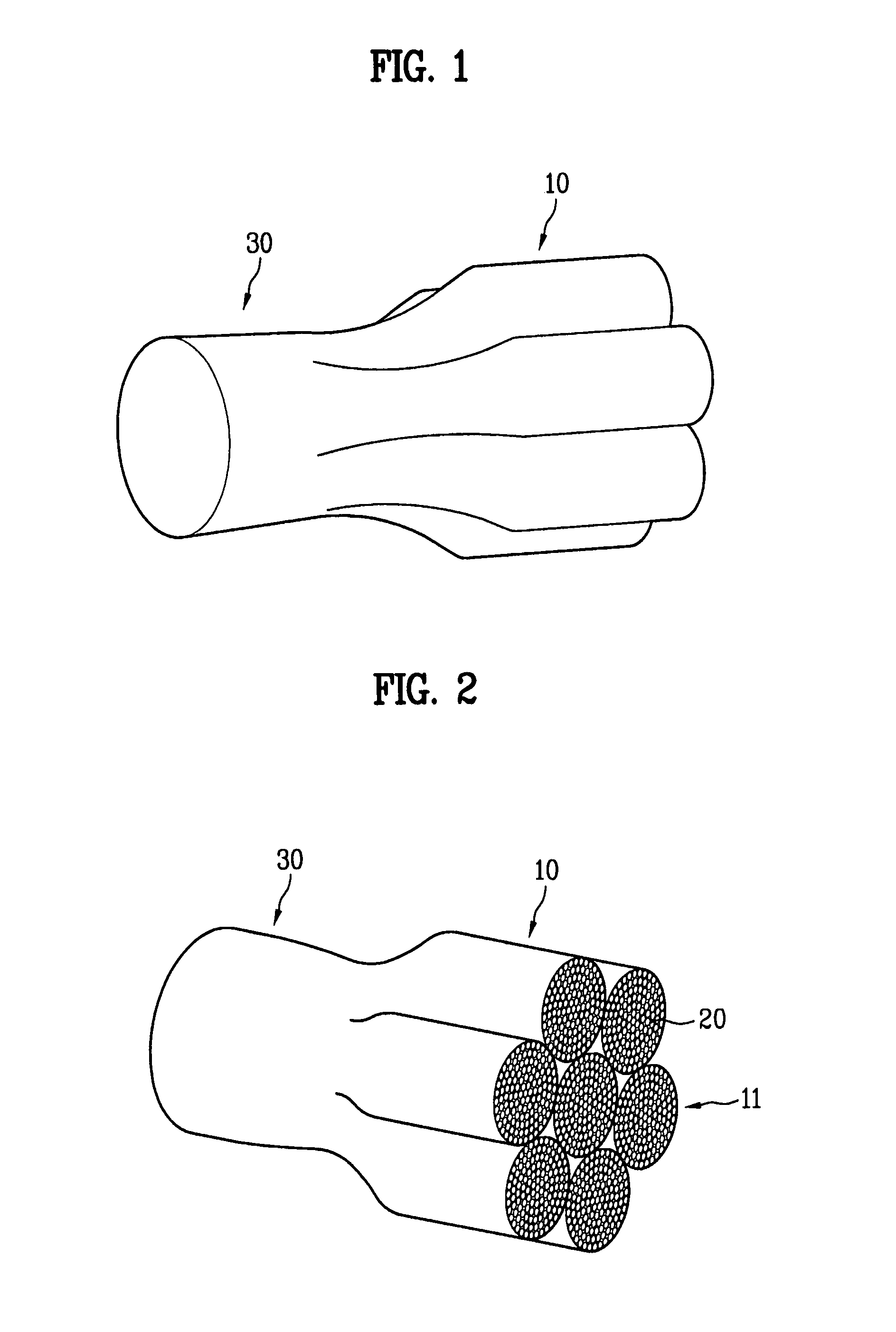
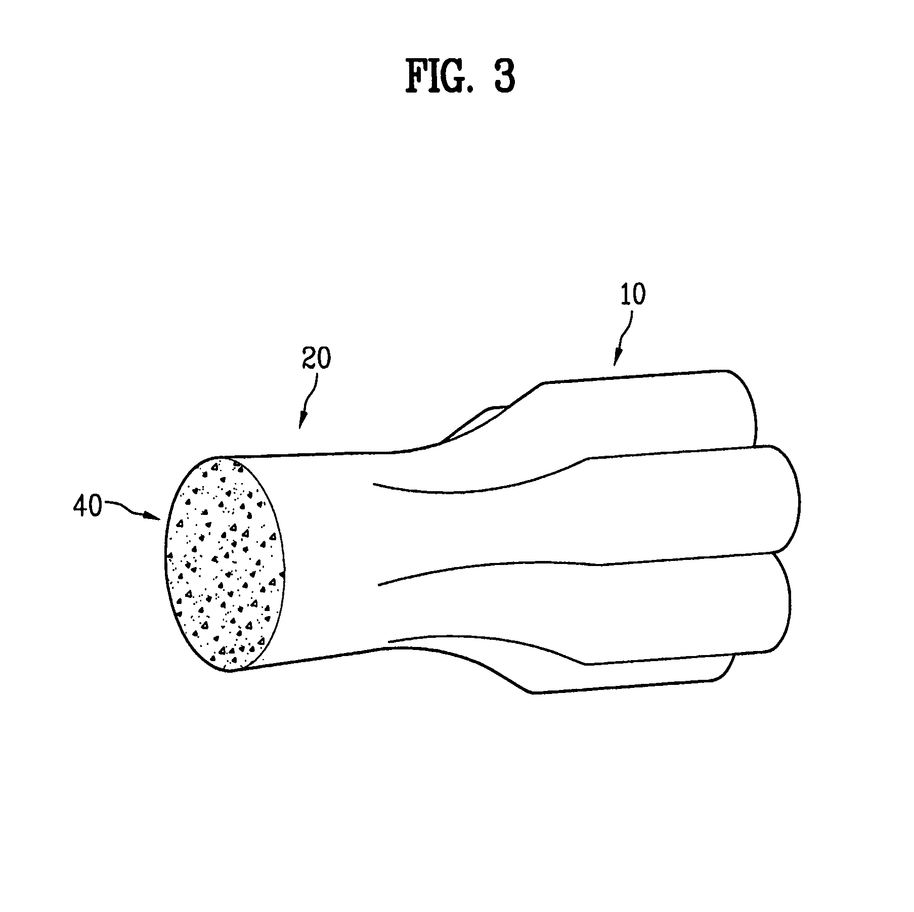
[0035]FIGS. 1 and 2 are perspective views illustrating one embodiment of an optical coupler in accordance with the present invention. With reference to FIGS. 1 and 2, an optical coupler includes first coupling units 10 and a second coupling unit 30. A guide hole 11, through which an external beam is incident on each of the first coupling units 10, is formed through each of the first coupling units 10.

[0036]The first coupling units 10 and the second coupling unit 30 are filled with an optical transmission medium 20.

[0037]Further, as shown in FIGS. 1 and 2, the first coupling units 10 are provided in a plural number, and beams of different colors are incident on the first coupling units 10 through the guide holes 11, are combined through the optical coupler, and are discharged to the second coupling unit 30.

[0038]Particularly, the coherence of laser beams is lowered using the optical coupler.

[0039]Preferably, laser beams of three primary colors of light, i.e., red, green, and blue, ar...

second embodiment

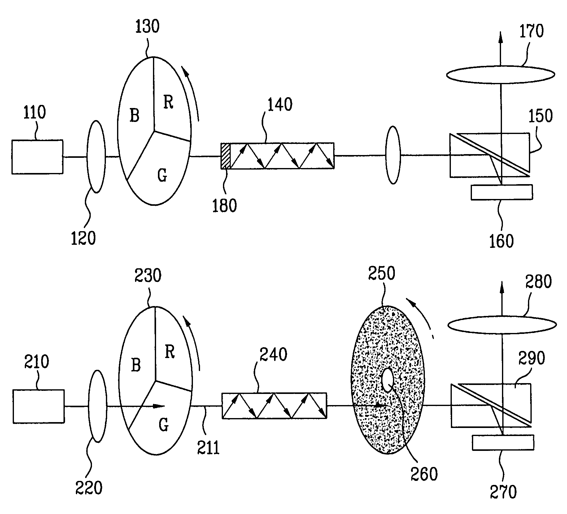
[0058]As shown in FIG. 5, a laser display device includes a laser beam combination unit 110, a rotary color separation unit 130, an optical path unit 140, an image display unit 160, and a projection lens unit 170. The optical path unit 140 includes a speckle elimination unit 180 provided on an incident plane thereof.

[0059]The laser beam combination unit 110 combines laser beams having narrow wavelength regions into white light. For example, the laser beam combination unit 110 combines laser beams of red (R), green (G), and blue (B) into white light. The white light is concentrated by a concentration lens 120.

[0060]The concentrated white light passes through the rotary color separation unit 130, which includes a combination of filters for respectively passing beams of different wavelengths and is rotated at a high speed. The white light is separated into beams according to wavelengths by the rotary color separation unit 130.

[0061]For example, in case that the rotary color separation ...

third embodiment

[0081]As shown in FIG. 9, a laser display device includes a laser beam combination unit 210, a rotary color separation unit 230, an optical path unit 240, a speckle elimination unit 250, an image display unit 270, and a projection lens unit 280.

[0082]The laser beam combination unit 210 combines laser beams having narrow wavelength regions into white light. For example, the laser beam combination unit 210 combines laser beams of red (R), green (G), and blue (B) into white light. If necessary, various light sources may be used.

[0083]The white light is concentrated by a concentration lens 220. The concentrated white light passes through the rotary color separation unit 230, which includes a combination of filters for respectively passing beams of different wavelengths and is rotated at a high speed.

[0084]The rotary color separation unit 230 separates the white light into beams according to wavelengths. For example, in case that the rotary color separation unit 230 includes a combinatio...


PUM


Abstract

A laser display device, which eliminates speckles generated in the transmission of laser beams and uniformly mixes laser beams of various colors, and an optical coupler therefor. The laser display device includes light sources emitting laser beams; an image display unit displaying an image by the laser beams; and a speckle elimination unit located on a path of the laser beams, and including at least one panel having an uneven part and disposed on an optical axis of the light sources.

Description

[0001]This application claims the benefit of Korean Patent Application No. 10-2006-0019524, filed Feb. 28, 2006 and Korean Patent Application No. 10-2006-0024014, filed Mar. 15, 2006, which are hereby incorporated by references as if fully set forth herein.BACKGROUND OF THE INVENTION[0002]1. Field of the Invention[0003]The present invention relates to a laser display device and an optical coupler therefor, and more particularly, to a laser display device, which eliminates speckles generated in the transmission of laser beams and uniformly mixes laser beams of various colors, and an optical coupler therefor.[0004]2. Discussion of the Related Art[0005]Recently, display devices using various light sources have been manufactured. Among various light sources, a laser light source has a wide color temperature, and is advantageous in that a displayed image are expressed in colors, which are close to natural colors, thus trying to be applied to a display field.[0006]However, when the laser ...

Claims


Application Information

Patent Timeline
Patent Type & Authority Patents(United States)
IPC IPC(8): G02B6/00G03B21/14
CPCG02B6/04Y10S385/901
Inventor SHIN, SUNG CHUL
Owner LG ELECTRONICS INC
Why Eureka
Try Eureka