
Currency processing device, method and system

a technology of currency bill and processing device, applied in the field of currency bill processing, can solve the problems of system too large for the operator to use while sitting down, system too wide for the operator and the system arranging the output receptacle horizontally became too wide to use while sitting or standing in one position, so as to achieve the effect of rapid evaluation of all bills

Inactive Publication Date: 2010-07-13
CUMMINS-ALLISON CORP
View PDF184 Cites 77 Cited by
  • Summary
  • Abstract
  • Description
  • Claims
  • Application Information

AI Technical Summary

Benefits of technology

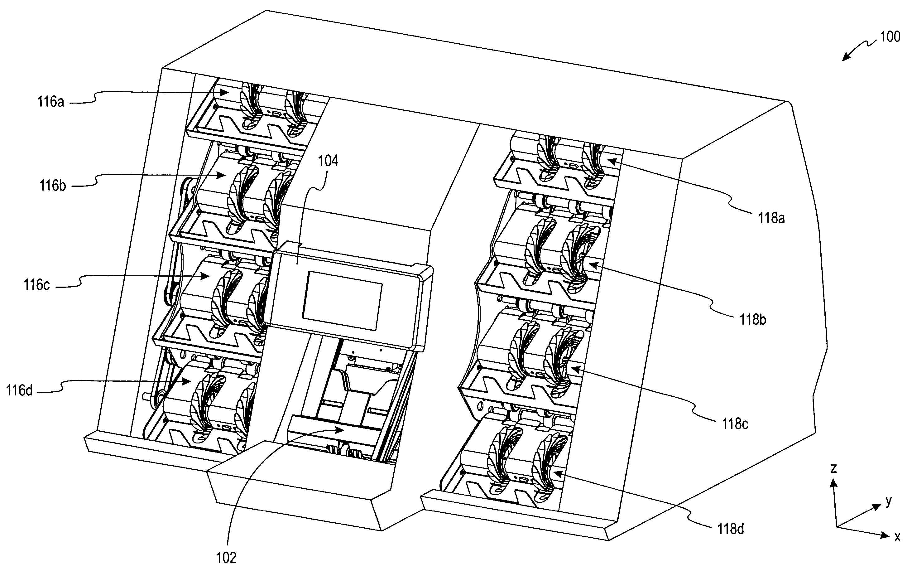
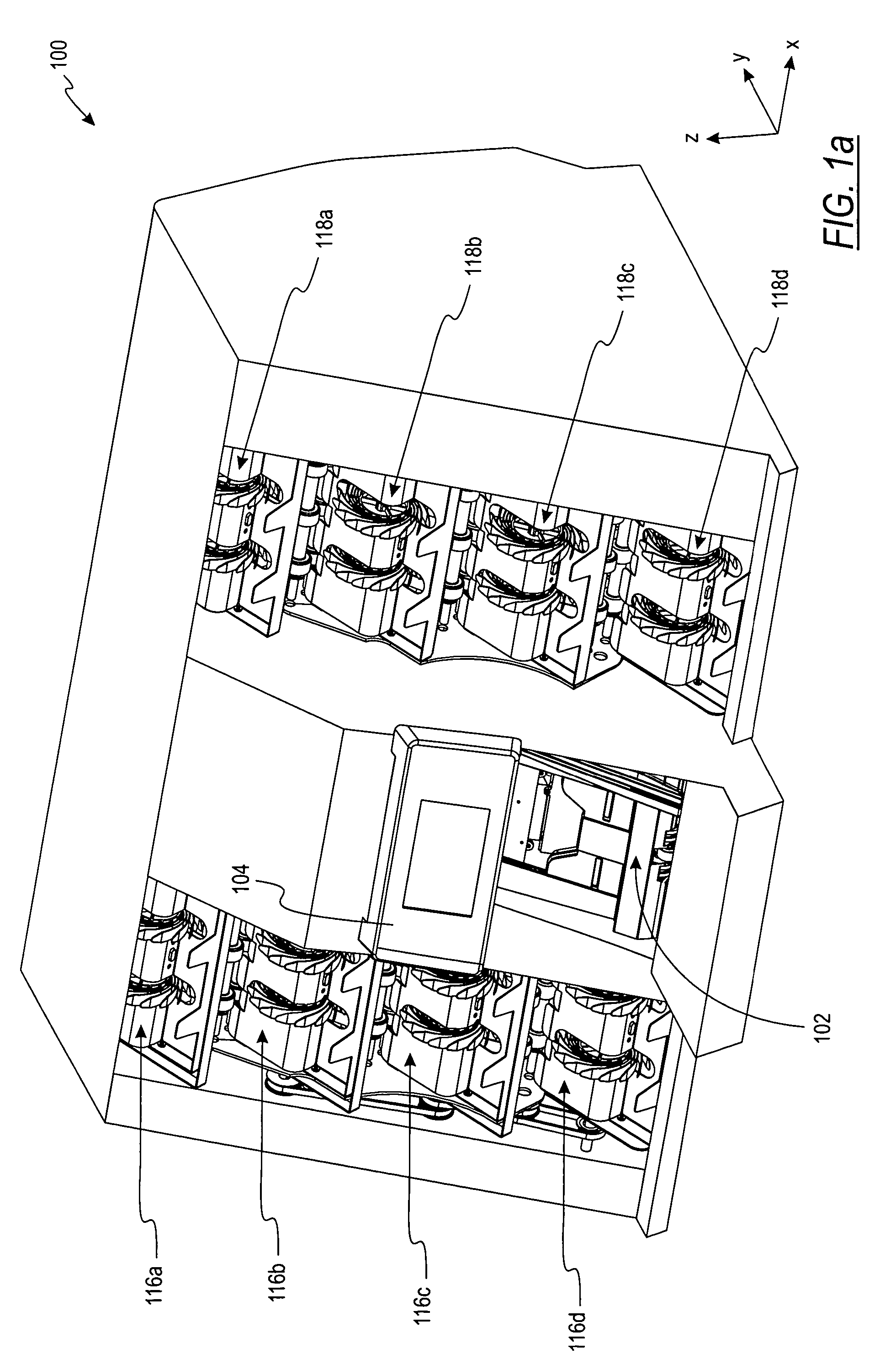
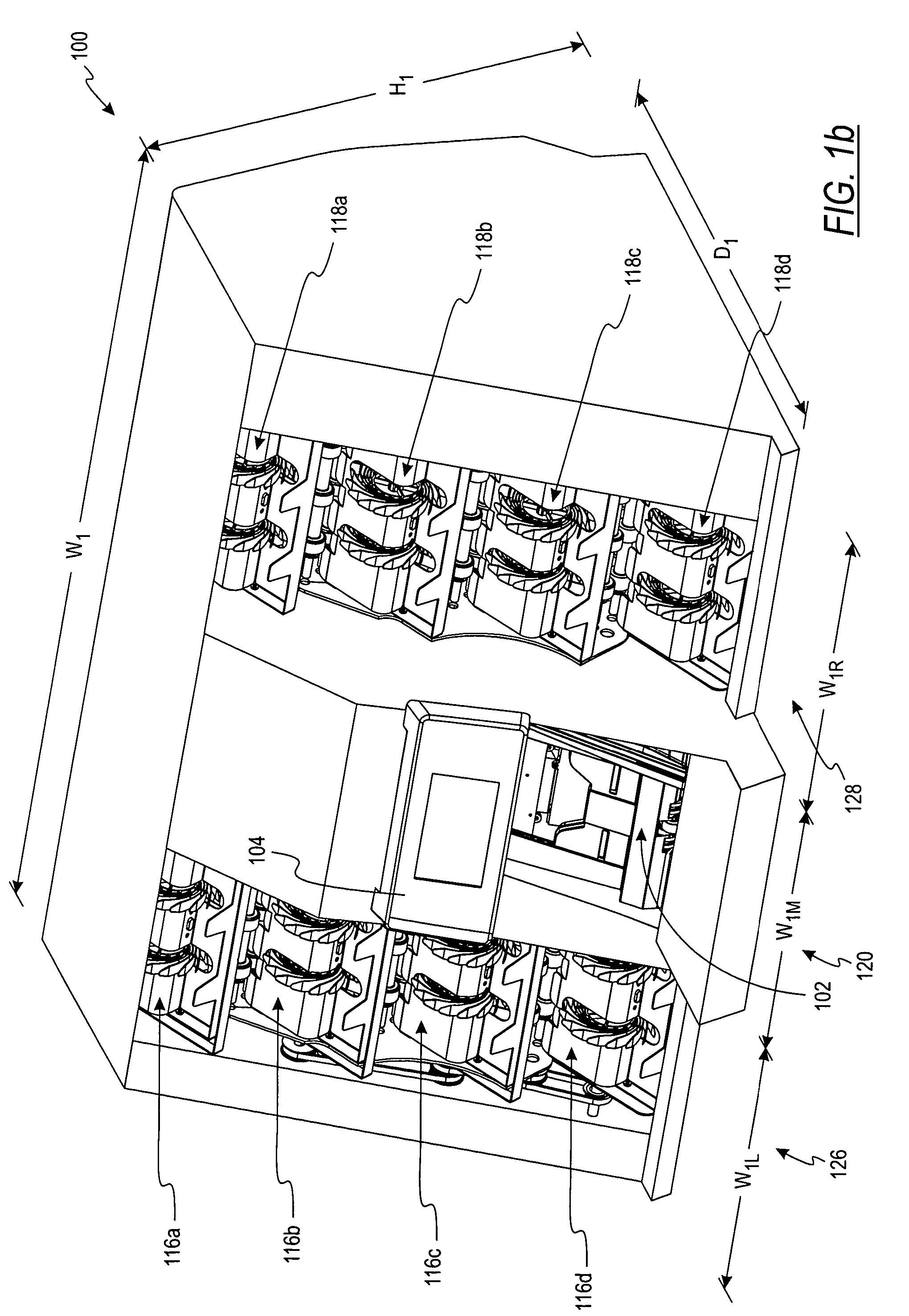
[0006]In some embodiments, a compact multi-pocket sorter for receiving a stack of currency bills and rapidly evaluating all the bills in the stack is provided. The device has an input receptacle for receiving a stack of bills to be evaluated and a number of output receptacles for receiving the bills after the bills have been evaluated. A transport mechanism transports bills, one at a time, from the input receptacle along a transport path to one of the output receptacles. A discriminating unit evaluates the bills, determining certain information concerning the bills. In some embodiments, at least one output receptacle is located to the left of the input receptacle and at least one output receptacle is located to the right of the input receptacle. Arranging the output receptacles on both the right and left of the input receptacle allows the output receptacles to be located in closer proximity to the input receptacle.

Problems solved by technology

Many of these systems have been very large—too large for the operator to be close to the input receptacle, operating panel, and output receptacles while remaining in one position.
The problem these machines faced is that after a few output receptacles are arranged in a vertical manner, the system is too tall for the operator to use while sitting down.
The systems arranging the output receptacles horizontally became too wide to use while seated or standing in one position.
Additionally, the existing systems for sorting currency have been expensive.

Method used


Image

  • Currency processing device, method and system
  • Currency processing device, method and system
  • Currency processing device, method and system

Examples


Embodiment Construction

[0069]FIG. 1a is a perspective view of one embodiment of a multi-pocket currency sorter or processing device 100. The device 100 has an input hopper or receptacle 102 adapted to receive a stack of currency bills to be processed. In some embodiments, the input hopper has a capacity of approximately 700 to approximately 800 currency bills. The device 100 also comprises a number of output receptacles or pockets which are laterally offset from the input hopper 102. As depicted in FIG. 1a, the shown embodiment comprises four output receptacles 116a-116d to the left of the input hopper 102 and four output receptacles 118a-118d to the right of the input hopper. The device may also comprise an operator or user interface 104 adapted to receive information from and / or provide information to an operator or user. In the embodiment illustrated in FIG. 1a, the interface 104 is in the form of a touchscreen. A controller coupled to the control panel causes the device to operate in a number of modes...


PUM

PropertyMeasurementUnit
heightaaaaaaaaaa
depthaaaaaaaaaa
widthaaaaaaaaaa

Abstract

According to one embodiment of the present invention, a currency processing device for receiving and processing a stack of currency bills is described. The currency processing device comprises an input receptacle for receiving a stack of bills to be processed, a plurality of output receptacles for receiving bills after the bills have been processed, a transport mechanism for transporting the bills from the input receptacle to the output receptacles, and a discriminating unit for examining the bills. The output receptacles are arranged such that a center of at least one output receptacle is laterally offset from a center of the input receptacle. The discriminating unit includes a detector positioned between the input receptacle and the output receptacles and is adapted to determine the denomination of bills.

Description

CROSS-REFERENCE TO RELATED APPLICATIONS[0001]This application is a continuation-in-part application of U.S. patent application Ser. No. 10 / 903,745, entitled “Currency Processing Device, Method And System” which was filed Jul. 30, 2004; U.S. patent application Ser. No. 10 / 903,745 claims priority to U.S. Provisional Patent Application Ser. No. 60 / 492,104, entitled “Currency Processing Device, Method And System” which was filed on Aug. 1, 2003 and U.S. Provisional Patent Application Ser. No. 60 / 580,662, entitled “Method And System For A Document Processing Device Utilizing Imaging” which was filed on Jun. 17, 2004, all of the above applications are incorporated herein by reference in their entirety.FIELD OF THE INVENTION[0002]The present invention relates to currency bill processing. Specifically, the present invention relates to an apparatus for currency bill denominating, authenticating, imaging and / or sorting.BACKGROUND OF THE INVENTION[0003]A variety of techniques and apparatus hav...

Claims


Application Information

Patent Timeline
Patent Type & Authority Patents(United States)
IPC IPC(8): G07F7/04G07F9/10B65H15/00G07D11/00
CPCB65H15/00G07D11/0084G07D11/0003G07D11/0021G07D11/0081B65H2301/33212B65H2301/33224B65H2701/1912B65H15/012G07D11/10G07D11/16G07D11/40G07D11/50
Inventor MAIER, KEN W.JONES, WILLIAM J.MENNIE, DOUGLAS U.BARANOWSKI, MAREKCHEN, YANMEI
Owner CUMMINS-ALLISON CORP
Learn More