
Method and apparatus for monitoring dynamic cardiovascular function using n-dimensional representations of critical functions

a dynamic and critical function technology, applied in the field of visualizing, perception, representation and computation of data, can solve problems such as errors in information analysis, and achieve the effect of quick and accurate analysis of complex and rapidly changing data, and quick assessment of patient status

Inactive Publication Date: 2005-01-13
UNIV OF UTAH RES FOUND
View PDF34 Cites 71 Cited by
  • Summary
  • Abstract
  • Description
  • Claims
  • Application Information

AI Technical Summary

Benefits of technology

[0006] It is desirable to provide a method, system, and apparatus, which facilitates the rapid and accurate analysis of complex and quickly changing data. Moreover, it is desirable that such a system and method include a graphic element that depicts the status of a patient's cardiovascular system by graphically showing blood pressure, blood flow, vascular tone and other cardiovascular variables. It is important that such a graphic element provide an anesthesiologist with the means to quickly assess the patient's status. It is also desirable that the element by comprised of subcomponents, which are linked together to show thereby the relationships of the various cardiovascular variables. Also, it is desirable that system and method be capable of analyzing time based, real-time, and historical data and that it be able to graphically show the relationships between various data.

Problems solved by technology

Conversely, a failure to use perceptual principles in the appropriate ways can lead to erroneous analysis of information.

Method used


Image

  • Method and apparatus for monitoring dynamic cardiovascular function using n-dimensional representations of critical functions
  • Method and apparatus for monitoring dynamic cardiovascular function using n-dimensional representations of critical functions
  • Method and apparatus for monitoring dynamic cardiovascular function using n-dimensional representations of critical functions

Examples


Embodiment Construction

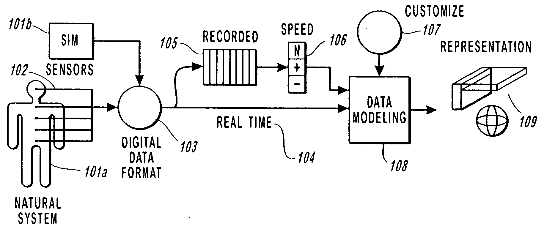
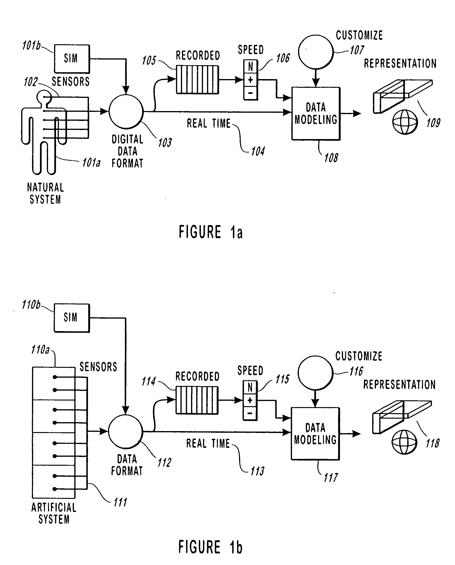
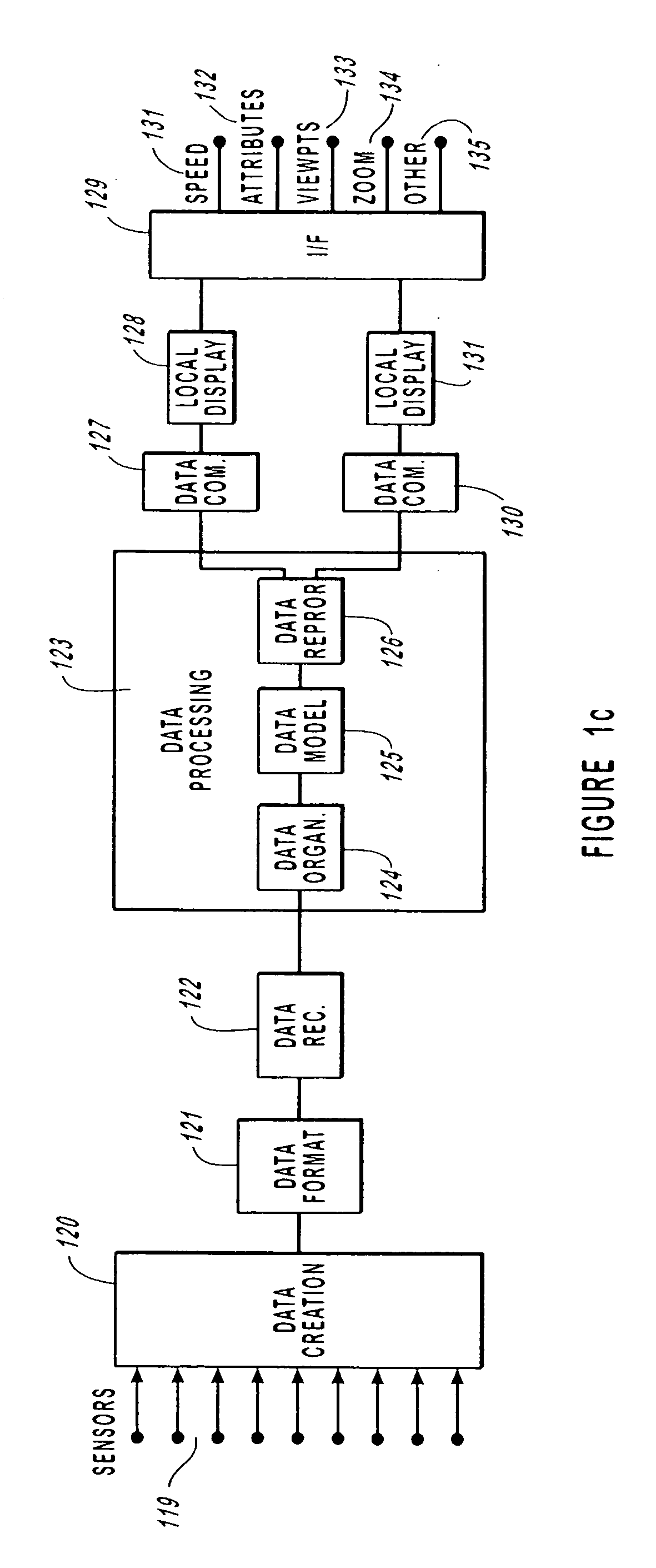
[0082] This invention is a method, system and apparatus for the visual display of complex sets of dynamic data. In particular, this invention provides the means for efficiently analyzing, comparing and contrasting data, originating from either natural or artificial systems. In its most common use the preferred embodiment of this invention is used to produce an improved cardiovascular display of a human or animal patient. This invention provides n-dimensional visual representations of data through innovative use of orthogonal views, form, space, frameworks, color, shading, texture, transparency, sound and visual positioning of the data. The preferred system of this invention includes one or a plurality of networked computer processing and display systems, which provide real-time as well as historical data, and which processes and formats the data into an audio-visual format with a visual combination of objects and models with which the user can interact to enhance the usefulness of t...


PUM


Abstract

A method, system, apparatus and device for the monitoring, diagnosis and evaluation of the state of a dynamic system is disclosed. This method and system provides the processing means for receiving sensed and / or simulated data, converting such data into a displayable object format and displaying such objects in a manner such that the interrelationships between the respective variables can be correlated and identified by a user. This invention provides for the rapid cognitive grasp of the overall state of a critical function with respect to a dynamic system. The system provides for displayed objects, which change in real-time to show the changes of the functions of the system. It is a highly flexible system which works with a wide variety of applications, including biological systems, environmental systems, engineering systems, economic systems, mechanical systems, chemical systems and the like. The device of this invention is adapted specifically to providing objects within a frame associated with other objects in a reference grid to provide a graphical representation of cardiovascular function.

Description

BACKGROUND OF THE INVENTION [0001] 1. Field of the Invention [0002] This invention relates to the visualization, perception, representation and computation of data relating to the attributes or conditions constituting the health state of a dynamic system. More specifically, this invention relates to the display and computation of cardiovascular data, in which variables constituting attributes and conditions of a dynamic physiological system can be interrelated and visually correlated in time as three-dimensional objects. [0003] 2. Description of the Related Art [0004] A variety of methods and systems for the visualization of data have been proposed. Traditionally, these methods and systems fail to present in a real-time multi-dimensional format that is directed to facilitating a user's analysis of multiple variables and the relationships between such multiple variables. Moreover, such prior methods and systems tend not to be specifically directed to display of a patient's cardiovasc...

Claims


Application Information

Patent Timeline
Patent Type & Authority Applications(United States)
IPC IPC(8): A61B5/00A61B5/02A61B5/0205G06T11/20
CPCA61B5/00A61B5/02G06T11/206A61B5/7445A61B5/0205
Inventor AGUTTER, JAMESSYROID, NOAHBERMUDEZ, JULIO C.ZHANG, YINQIHOLMES, MICHAEL E.DREWS, FRANKSTRAYER, DAVID LEEALBERT, ROBERT WILLIAMWESTENSKOW, DWAYNE R.
Owner UNIV OF UTAH RES FOUND
Learn More