Electronic drum pedal

a technology of electronic drums and pedals, applied in the direction of stringed musical instruments, instruments, musical instruments, etc., can solve the problems of unnecessarily slow and difficult control, insufficient sound, and inability to quickly successively beat the drums

Inactive Publication Date: 2009-05-12
STEELE MARK DAVID
View PDF26 Cites 5 Cited by
  • Summary
  • Abstract
  • Description
  • Claims
  • Application Information

AI Technical Summary

Benefits of technology

[0003]The present invention is directed to a drum pedal whereby raising and lowering the foot can trigger two beats instead of one, thus creating sounds at twice the rate of conventional pedals.
[0004]The disclosed invention reduces the force required to produce triggering, allowing increased speed and control. In addition, the disclosed invention reduces the momentum inherent in the device, which allows a very rapid return to the start position, increasing speed and control. The disclosed drum pedal may include an adjustable return spring tension, and only one moving part. The disclosed pedal facilitates very rapid, controlled drum beats with a single foot, retaining the use of the hi-hat instrument.

Problems solved by technology

If the throw of the beater is shortened or the mass is reduced, there is often not enough sound produced.
The problem is that the mass and long throw weight inherent in conventional pedals make them unnecessarily slow and hard to control.
The inherent inertia of existing drum pedals makes rapid successive drum beats impossible, and the long arc of travel of the beater makes timing difficult.

Method used


Image

  • Electronic drum pedal
  • Electronic drum pedal
  • Electronic drum pedal

Examples


Embodiment Construction

[0032]Detailed descriptions of the preferred embodiment are provided herein. It is to be understood, however, that the present invention may be embodied in various forms. Therefore, specific details disclosed herein are not to be interpreted as limiting, but rather as a basis for the claims and as a representative basis for teaching one skilled in the art to employ the present invention in virtually any appropriately detailed system, structure or manner.

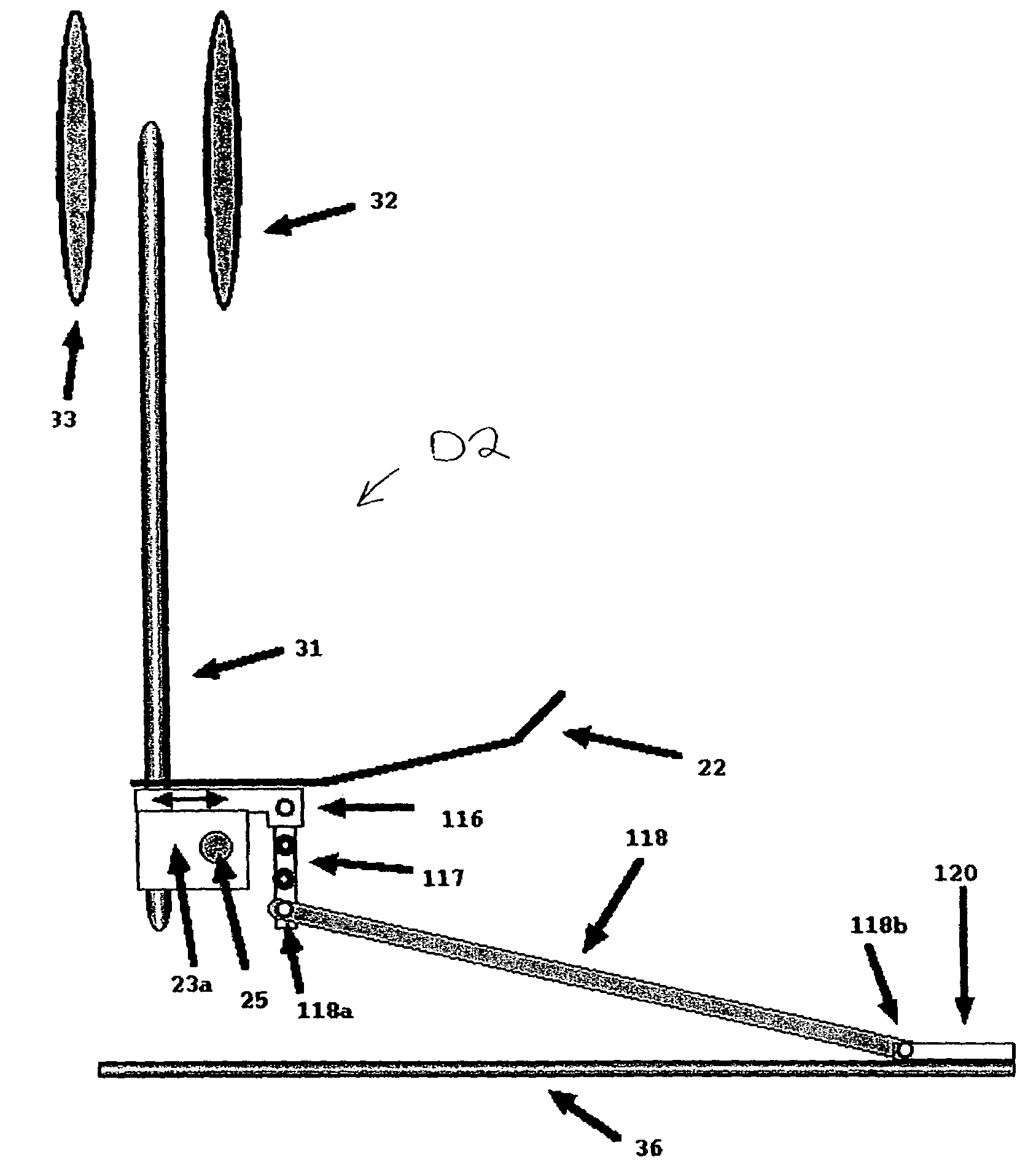
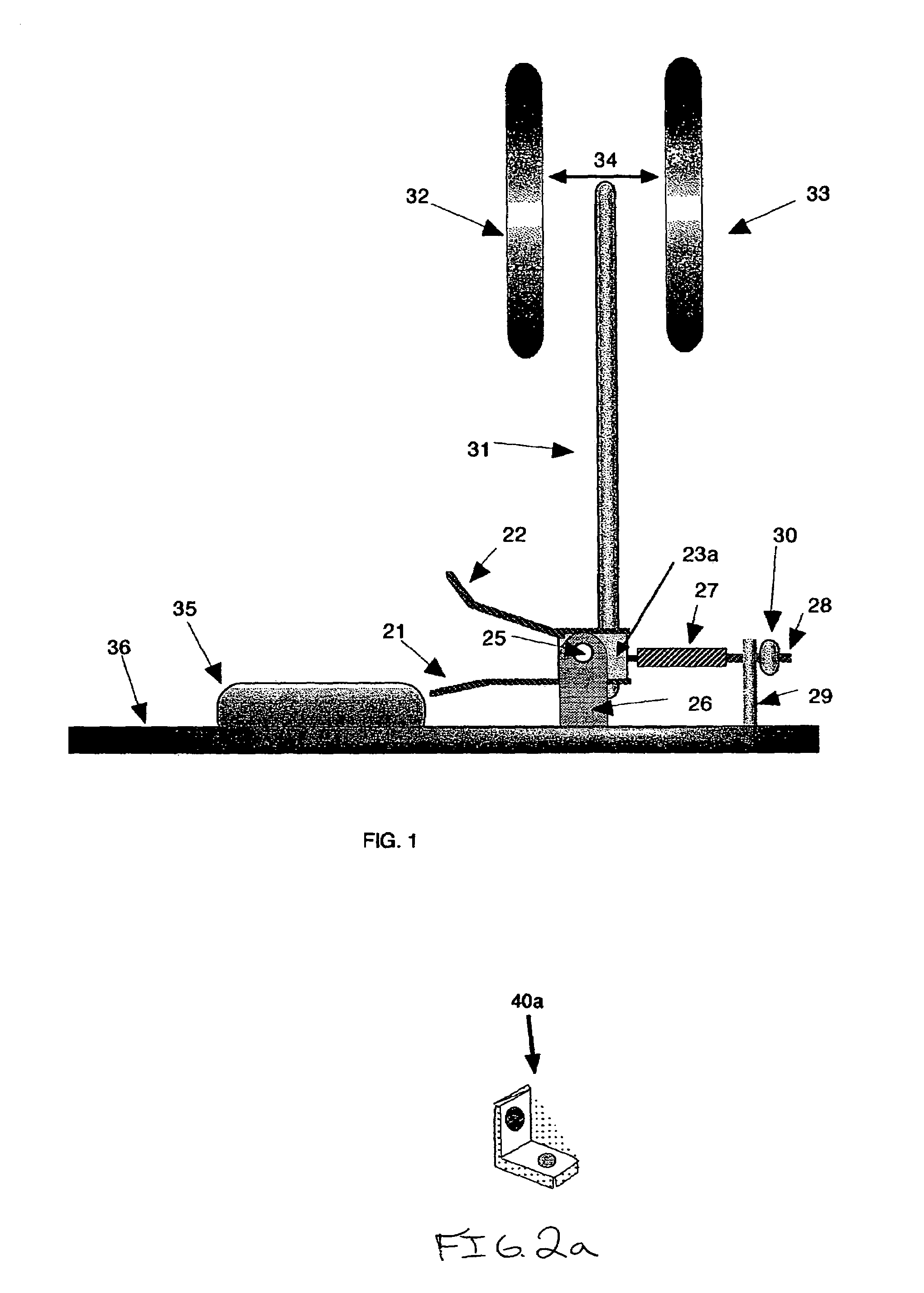
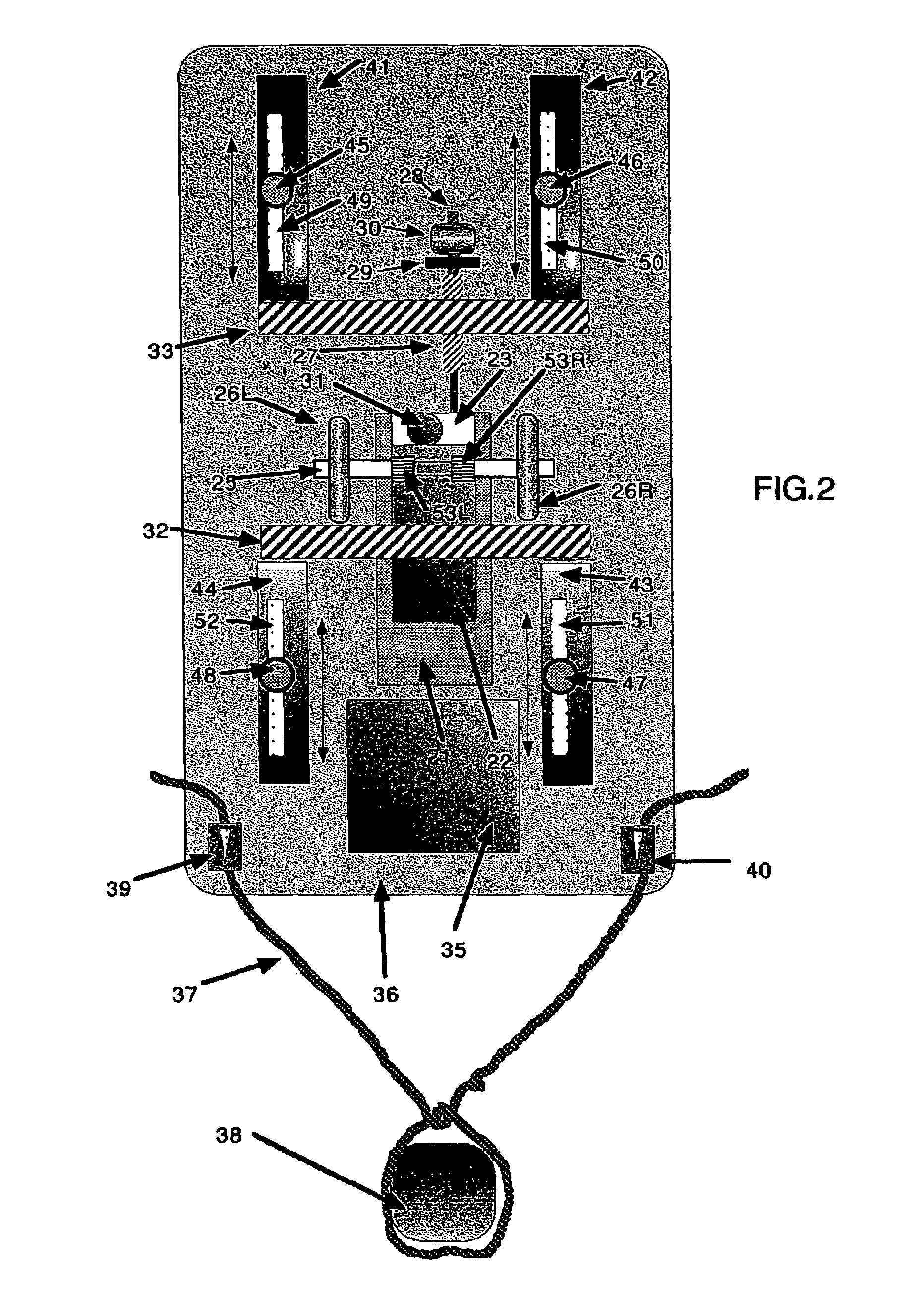
[0033]FIG. 1 shows a drum pedal assembly for electronic drums in accordance with one embodiment of the invention, wherein the parts identical to those shown in FIGS. 2 through 8 are designated by the same reference numerals. The disclosed drum pedal includes a lower pedal tab 21, or other type of extension, and an upper pedal tab 22, or other type of extension. Lower tab 21 and upper tab 22 are connected to a hub body 23a to form the main pedal assembly. This assembly rotates about an axle 25 which is suspended by axle stands 26 that...


PUM


Abstract

A foot pedal for electronic drums includes a lower tab or pedal or other extension for triggering by pressing down, and an upper tab or pedal or other extension for triggering by raising the foot. Also included is the joining of the upper and lower extensions (tab, pedal or other) into a pedal assembly that includes: a hinge or axle or other device which allows the pedal assembly to rotate in an arc; a striking device (stick, rod or other) that is attached to the pedal assembly and hits impact sensitive electronic drum triggering devices (pads, tubes or others); and an elastic device or spring which returns the pedal assembly to the neutral (at-rest) position.

Description

CROSS REFERENCE TO RELATED APPLICATION AND CLAIM TO PRIORITY[0001]This application is a continuation-in-part of application Ser. No. 10 / 873,344, filed Jun. 21, 2004 now U.S. Pat. No, 7,074,997, for Mark D. Steele, the disclosure of which is incorporated herein by reference and to which priority is claimed under 35 U.S.C. §120.FIELD OF THE INVENTION[0002]The present invention is directed to an apparatus for triggering electronic drums. The apparatus includes a base, a hub body pivotably connected to the base, an upper tab extending outwardly from the hub body, and a pedal spaced from the upper tab to form a space therebetween for receiving a user's toes. A linkage has a first portion pivotally connected to the hub body and a second portion pivotally connected to the pedal, thereby pivotally connecting the pedal to the hub body. First and second impact sensitive electronic triggering devices are provided. An elongate striking device has a first end connected to the hub body and a seco...

Claims


Application Information

Patent Timeline
Patent Type & Authority Patents(United States)
IPC IPC(8): G10D13/02
CPCG10D13/006G10D13/11
Inventor STEELE, MARK, DAVID
Owner STEELE MARK DAVID
Why Eureka
Try Eureka