Mould mat for producing bone cement pellets

a mould mat and pellet technology, applied in the field of mould mats and methods for producing bone cement pellets, can solve the problems of large area of the surface of the mould mat that does not contain any cavities, waste of expensive bone substitute materials, messy and time-consuming procedure for pasting cement into the cavities of the prior art, etc., to facilitate rapid and easy filling of cavities

Active Publication Date: 2013-12-26
BIOCOMPOSITES
View PDF6 Cites 4 Cited by
  • Summary
  • Abstract
  • Description
  • Claims
  • Application Information

AI Technical Summary

Benefits of technology

[0022]A flat device, such as a scraper or spreader, is typically used to fill the cavities with the bone cement. The device may be of a substantially similar width to the mould mat, or alternatively it may be of a similar width to the width of the area occupied by the cavities on the mould mat. This facilitates the rapid and easy filling of the cavities with hardenable bone cement paste. The scraper or spreader device will typically be made from a rigid or semi-rigid material which is biologically acceptable such as a polymeric material including, but not limited to, polypropylene, polyethylene, polyvinyl chloride, polyacetal, or any other mechanically similar material. The scraper or spreader device is typically thicker at the handle part, around about 3 mm to about 4 mm thick, and typically tapers down to around about 1 mm to about 2 mm thickness at its edge where it engages the mat; this allows for ease of handling by the surgeon of the scraper.
[0023]A second embodiment of a scraper or spreader device that may be used in accordance with the invention is a flat device having a substantially ‘L’-like shape, where the edge of the scraper or spreader device that engages the mould mat is substantially of a similar width to that of the mould mat, or alternatively it may be of a similar width to the width of the area occupied by the cavities on the mould mat. This scraper or spreader device facilitates rapid and easy filling of the cavities with a hardenable bone cement paste. This second embodiment would also be, typically, made from a rigid or semi-rigid material including but not limited to, polypropylene, polyethylene, polyvinyl chloride, polyacetal, or any other mechanically similar material. The top of the ‘L’ shaped scraper or spreader device is typically thicker as it makes up the handle part of the scraper or spreader device and is typically around 3 mm to about 4 mm thick. This allows for ease of handling by the user, such as a surgeon, of the scraper or spreader device. The scraper or spreader device typically tapers down from the handle to around 1 mm to 2 mm thickness at its edge where it engages the mat.

Problems solved by technology

Pasting the cement into the cavities of a mould mat of the prior art can be a messy and time consuming procedure, particularly when using the small mixing spatula for this purpose.
Additionally, mould mats of the prior art often contain an array of cavities whereby the distance between adjacent cavities is large relative to the cavity diameter, resulting in a large area of the surface of the mat that does not contain any cavities.
This, typically, also results in a waste of expensive bone substitute material as it is difficult to ensure that all of the hardenable bone cement is used to fill all of the mould cavities.
The use of the small mixing spatula to paste all of the hardening cement into the mould cavities can take longer than the setting time of the cement such that the cement hardens and sets before it is all used to fill the mould cavities.
The extraction of the bone pellets through flexing of the mat can be difficult as the mat may not flex very well, or the pellets may become stuck within the mat.
The surgeon therefore is faced with the possibility of having insufficient pellets for the surgical site due to the surgeon being unable to extract some of the pellets from the mould mat of the prior art by flexing it.
Those that have been extracted may have rough edges due to the bone cement residue that has been left on the mould mat surface and has hardened.
In order to provide the surgeon with the option to produce a range of pellet sizes, or shapes, and also additional quantity of pellets the mould mat may be excessively large or indeed two mould mats having cavities of differing shapes or sizes may be required.
Additional mould mats add to both cost and packaging requirements which can further impact on sterilization issues and storage volumes.
There is also an increase of bone cement wastage where bone cement has remained within the area between the cavities on the surface of the mould mat.

Method used


Image

  • Mould mat for producing bone cement pellets
  • Mould mat for producing bone cement pellets
  • Mould mat for producing bone cement pellets

Examples


example 1

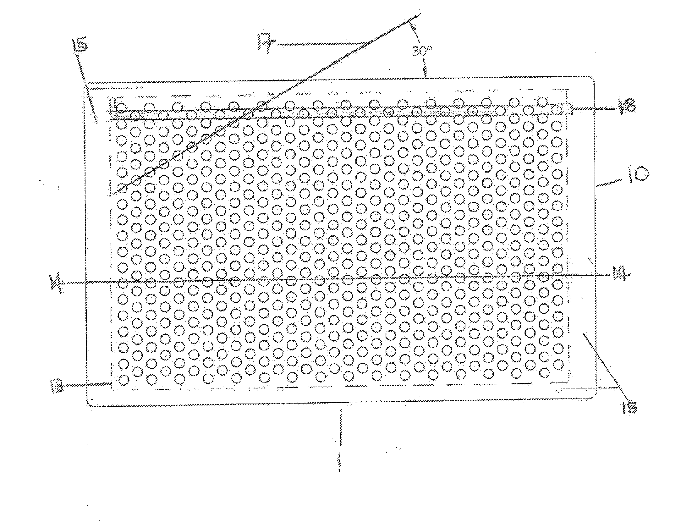
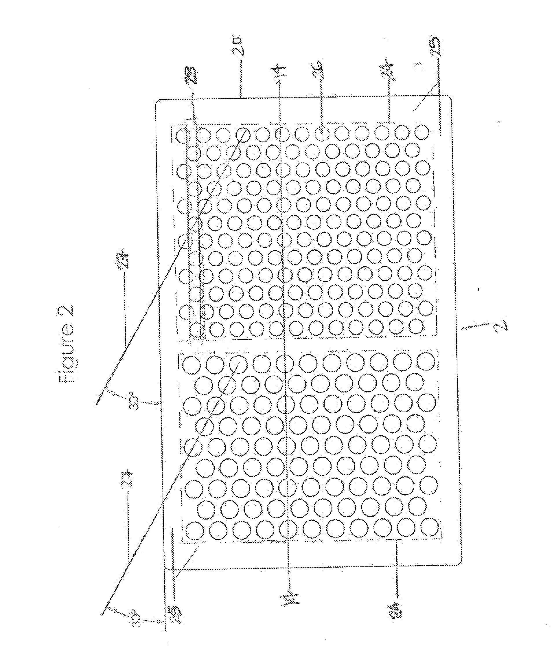
[0068]A two sided, flat rectangular mould mat having a width of between 72 mm-122 mm, a length of between 132 mm-179 mm and a thickness of between 6 mm-12 mm was produced using a flexible polymeric material, such as a silicone rubber or a thermoplastic elastomer (TPE). The first side contains an array of 560 cylindrical cavities of 3 mm diameter having a hemispherical closed end arranged in a hexagonal grid pattern with rows of cavities having a diagonal offset of about 30 degrees, as shown in FIG. 1. The second side contains two arrays of cylindrical cavities having a hemispherical closed end, one array consists of 150 cavities of 4.8 mm diameter and the other array consists of 95 cavities of 6 mm diameter. Both arrays are arranged in a hexagonal grid pattern with cavity rows having a diagonal offset of 30 degrees, as shown in FIG. 3.

example 2

[0069]A flat, rectangular mould mat was manufactured from a flexible silicone rubber having dimensions; width=10 cm, length=16 cm, thickness=0.8 cm, where both sides have a plurality of cavities for moulding bone cement pellets. The cavities on both sides are arranged in an array of rows and columns where the rows run across the width of the mould mat and the columns run down the length of the mould mat. Each adjacent row of cavities is offset towards the long edge of the mould mat such that each column of cavities then becomes non-parallel to the long axis of the mould mat. Off-setting each adjacent row by a distance equivalent to approximately half the diameter of a cavity results in the columns aligning with an axis that is approximately about 20 degrees to the long axis of the mould mat. All the cavities on a first side of the mould mat have a diameter of 3 mm and depth of 3.5 mm while all cavities on a second side of the mould mat have a diameter of 4.8 mm and depth of 5 mm. Al...


PUM

PropertyMeasurementUnit
diameteraaaaaaaaaa
thicknessaaaaaaaaaa
widthaaaaaaaaaa

Abstract

A means to prepare bone cement pellets comprising bone cement paste which hardens through hydration a flexible mould mat having pellet cavities on both sides and a scraper for pasting the bone cement paste in to the pellet cavities where the paste is allowed to harden.

Description

BACKGROUND OF INVENTION[0001]The present invention provides a mould mat and method for producing bone cement pellets, i.e. hardened pellets of a bioabsorbable bone substitute material suitable for the treatment of bone disorders and filling of bony voids or defects of the skeletal system. In particular, although not exclusively, the present invention provides a convenient and simple means to produce moulded, hardened pellets (e.g. cylindrical pellets) of a calcium-based bone cement having a range of sizes for the treatment of bone disorders and filling bone defects, with minimal bone cement wastage.[0002]The use of calcium salt based bone substitute materials is common practice in orthopaedic surgical procedures for the filling of bony voids or gaps of the skeletal system caused by trauma, disease or surgery. These materials when implanted are intended to resorb and be replaced by new bone as they do so. They can consist of a range of different calcium based salts incorporating sulp...

Claims


Application Information

Patent Timeline
Patent Type & Authority Applications(United States)
IPC IPC(8): A61L33/00B27N5/00
CPCA61L33/0005B27N5/00A61F2/28A61F2/4644A61F2002/30227A61F2002/30957A61F2310/00353A61F2002/2835A61F2002/2839
Inventor LAYCOCK, PHILLIPCOOPER, JOHNWATERS, RUSSELLCOLCLOUGH, JOHNMAALE, GERHARD
Owner BIOCOMPOSITES
Why Eureka
Try Eureka