
Calibrated masonry guide line support and method

a technology of guide line and support, applied in the field of masonry, can solve the problems of brick walls or facades, not designed to be easily moved in a vertical direction, and not provide for rapid transition of lines between two or more predetermined positions, so as to facilitate the rapid and aligned placement of bricks

Inactive Publication Date: 2008-12-11
DARTY JERRY D
View PDF10 Cites 8 Cited by
  • Summary
  • Abstract
  • Description
  • Claims
  • Application Information

AI Technical Summary

Benefits of technology

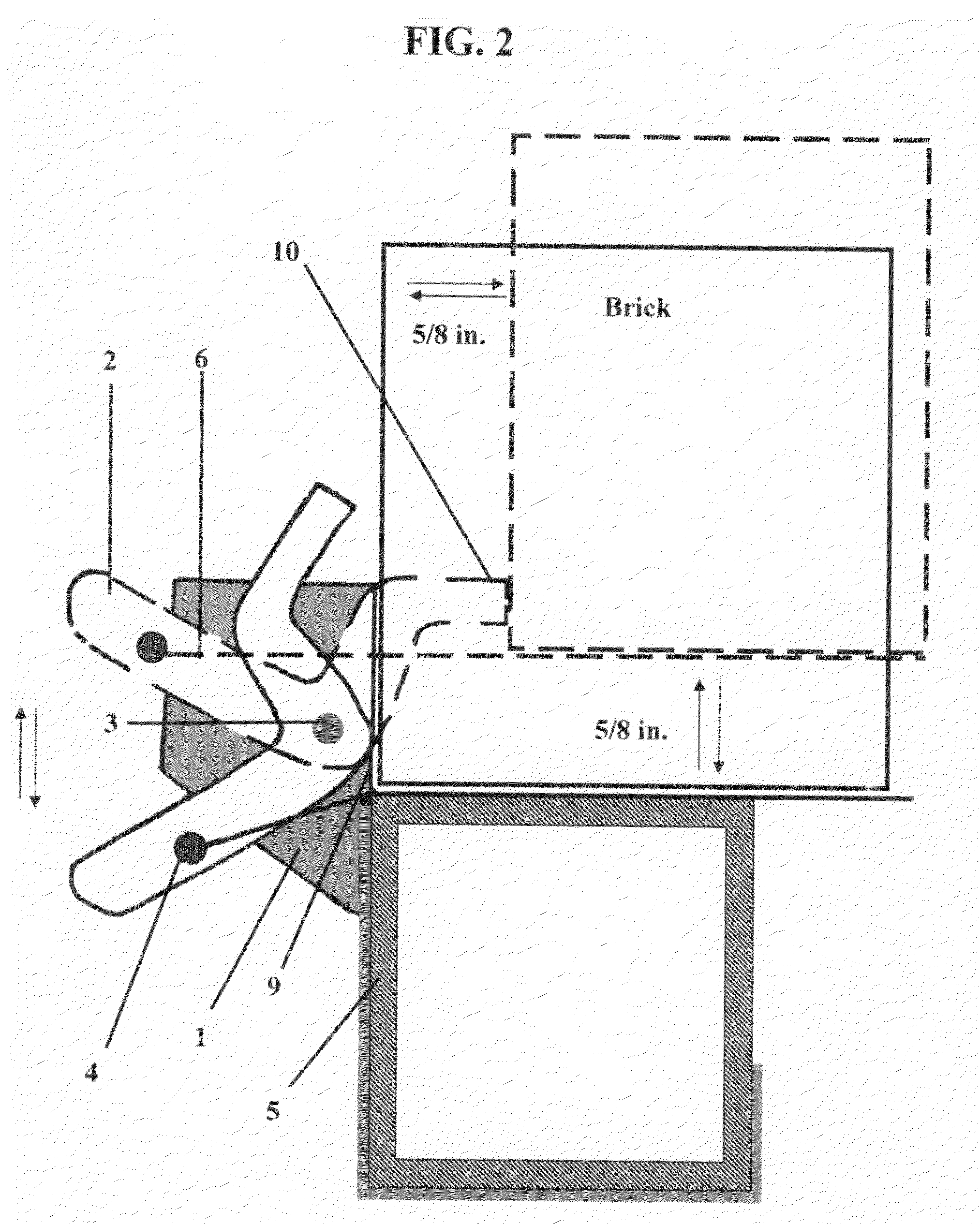
[0012]The present invention is an apparatus and method for guiding the placement of bricks in a wall or facade in which the bricks are placed in a plurality of parallel planes offset by one or more predetermined distances. The apparatus comprises first and second members joined by a pivot or hinge mechanism that allows them to move relative to one another. The first member serves to hold the apparatus to a plumbed post located at the base of the wall or facade to be built and provides a stop for placement of the first brick in a course. The second member comprises a line support, a stop, and a protrusion for moving second member relative to the first member. When the apparatus is held to the post and attached to a line, moving the protrusion of the second member moves the attached line to a preset distance from the post. The use of the apparatus at both ends of a wall building site facilitates the rapid, aligned placement of bricks in a plurality of parallel planes.

Problems solved by technology

Often, however, brick walls or facades include complex structures such as decorative quoins, projective brick at windows and doors, arches, and solider rowlock that require bricks to be placed in multiple, parallel planes offset by set distances.
The apparatus disclosed in the '826 patent is affixed to a wall and is not designed to be easily moved in a vertical direction to guide the laying of multiple courses of bricks.
While the line support can be moved to variable distances from the wall supporting the apparatus, it does not provide for rapid transitions of the line between two or more predetermined positions.

Method used


Image

  • Calibrated masonry guide line support and method
  • Calibrated masonry guide line support and method
  • Calibrated masonry guide line support and method

Examples


first embodiment

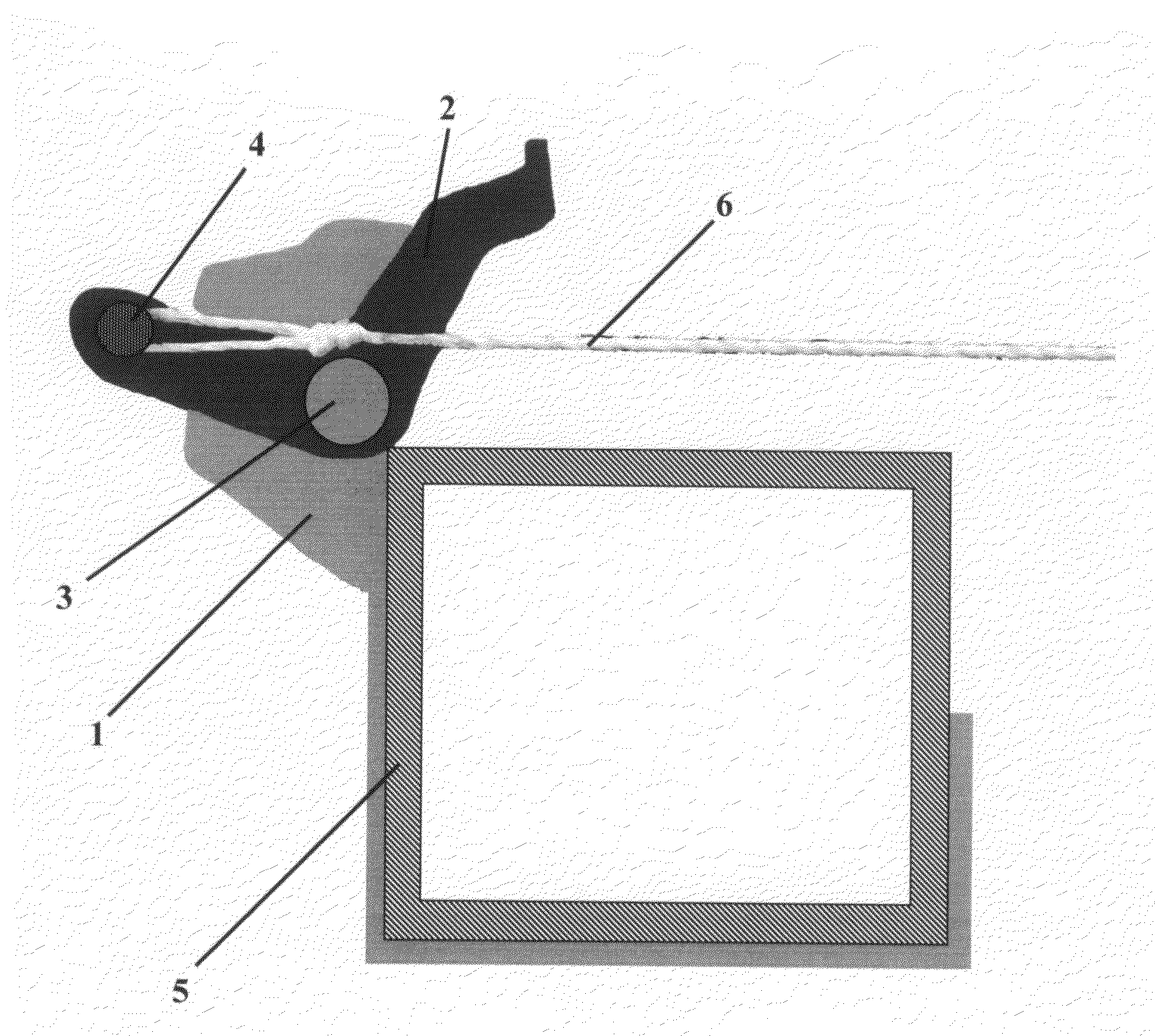
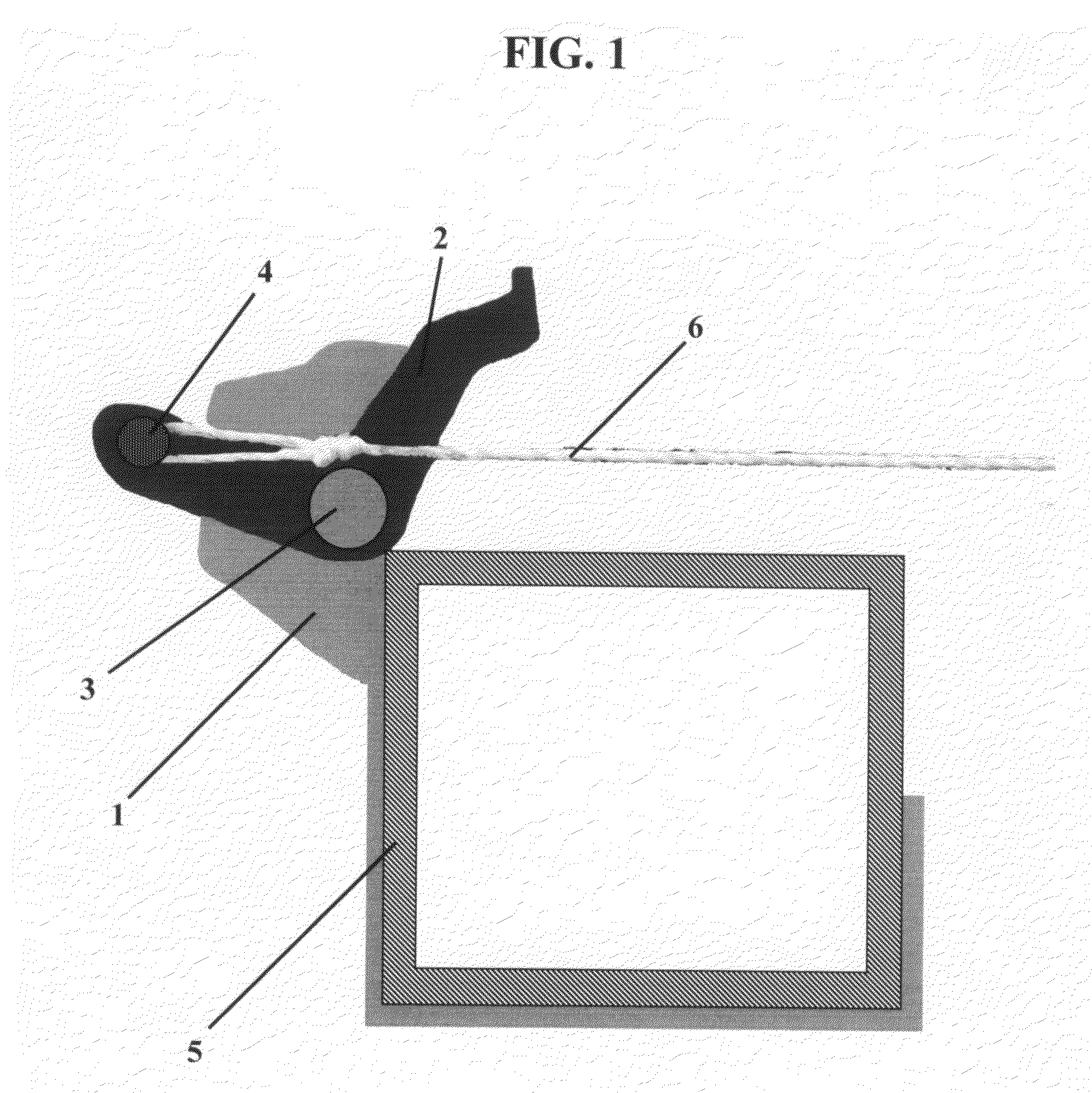
[0018]the calibrated guide line support is shown in FIG. 1. The support comprises a rigid first member 1 connected to a second rigid member 2 though a hinge 3. Rigid member 1 is shaped, in this instance, to conform to the cross-section of a hollow aluminum 2×2 corner post 5. Rigid member 2 comprises a line support 4 to which a guide line 6 has been fastened.

[0019]The rigid members, hinge, and line support are preferably made of aluminum, steel, or hard plastic but may be made from any number of materials capable of withstanding the stresses placed on the apparatus during use. The first rigid member 1 may be shaped to conform to a variety of posts or other plumbed masonry guides such as 2×2 inch or other size posts, angle irons, and T-shaped posts. The portion of first member 1 conforming a corner post and the portion attached to second member 2 may be formed from a single piece of metal or plastic, for example, or me be formed by welding two pieces of metal or otherwise fusing or fa...

second embodiment

[0021]FIG. 3 is a top view photograph of the calibrated guide line support in which a first region 7 the first member 1 is shaped to conform to the cross-section of an angle iron and a second region 8 of the first member is shaped to form handle to facilitate the movement of the line support in a vertical direction along the angle iron. Also shown are brick stops 9 and 10 formed by portions of members 1 and 2, respectively, pivot 3 joining members 1 and 2, and line support 4. A top view photograph of an embodiment of the invention wherein the first member is adapted for attachment to a 2 in by 2 in corner pole is shown in FIG. 4. The portion of member 1 adapted to conform to the angle iron or corner pole may comprise a flexible material or other means for producing a force adequate to hold the guide line support in place on the corner pole with no guide line attached.

[0022]FIG. 5 is an end-on photograph illustrating first guide line support on a first corner pole (foreground and in ...


PUM


Abstract

The present invention is an apparatus and method for guiding the placement of bricks in a wall or facade in which the bricks are placed in a plurality of parallel planes offset by one or more predetermined distances. The apparatus comprises first and second members joined by a pivot or hinge mechanism that allows them to move relative to one another. The first member serves to hold the apparatus to a plumbed post located at the base of the wall or facade to be built and provides a stop for placement of the first brick in a course. The second member comprises a line support, a stop, and a protrusion for moving second member relative to the first member. When the apparatus is held to the post and attached to a line, moving the protrusion of the second member moves the attached line to a preset distance from the post. The use of the apparatus at both ends of a wall building site facilitates the rapid, aligned placement of bricks in a plurality of parallel planes.

Description

CROSS-REFERENCE TO RELATED APPLICATIONS[0001]Not ApplicableSTATEMENT REGARDING FEDERALLY SPONSORED RESEARCH OR DEVELOPMENT[0002]Not ApplicableINCORPORATED-BY-REFERENCE OF MATERIAL SUBMITTED ON A COMPACT DISC[0003]Not ApplicableBACKGROUND OF THE INVENTION[0004]1. Field of the Invention[0005]The present invention relates generally to the art of masonry and is directed to a tool, apparatus, or assembly and corresponding method for guiding the placement of bricks in plumb and horizontal orientations, particularly in the construction of walls and facades having bricks that lie in two or more vertical planes.[0006]2. Description of Related Art[0007]Brick walls and facades are generally built by laying successive courses of brick or stone on top of another. Most commonly, the wall or facade is planar, having no bricks lying out of the plane of the wall. A variety of devices and methods for guiding the placement of bricks in vertical and horizontal directions are provided in the prior art t...

Claims


Application Information

Patent Timeline
Patent Type & Authority Applications(United States)
IPC IPC(8): G01C15/00G01C15/10
CPCE04G21/18E04G21/1841
Inventor DARTY, JERRY D.
Owner DARTY JERRY D
Learn More