Burner

a burner and combustion chamber technology, applied in the field of burners, can solve the problems of self-excited combustion oscillations in the operating range of burners with premixtures, in particular in gas turbines, and achieve the effect of simple and extended combustion rang

Active Publication Date: 2010-07-13
SIEMENS ENERGY GLOBAL GMBH & CO KG
View PDF20 Cites 4 Cited by
  • Summary
  • Abstract
  • Description
  • Claims
  • Application Information

AI Technical Summary

Benefits of technology

[0004]The object of the invention is therefore to demonstrate a burner in which a stable range for combustion is extended in a simple manner.

Problems solved by technology

The operating range of burners with premixtures, in particular in gas turbines, is limited by self-excited combustion oscillations.

Method used


Image

  • Burner
  • Burner
  • Burner

Examples


Embodiment Construction

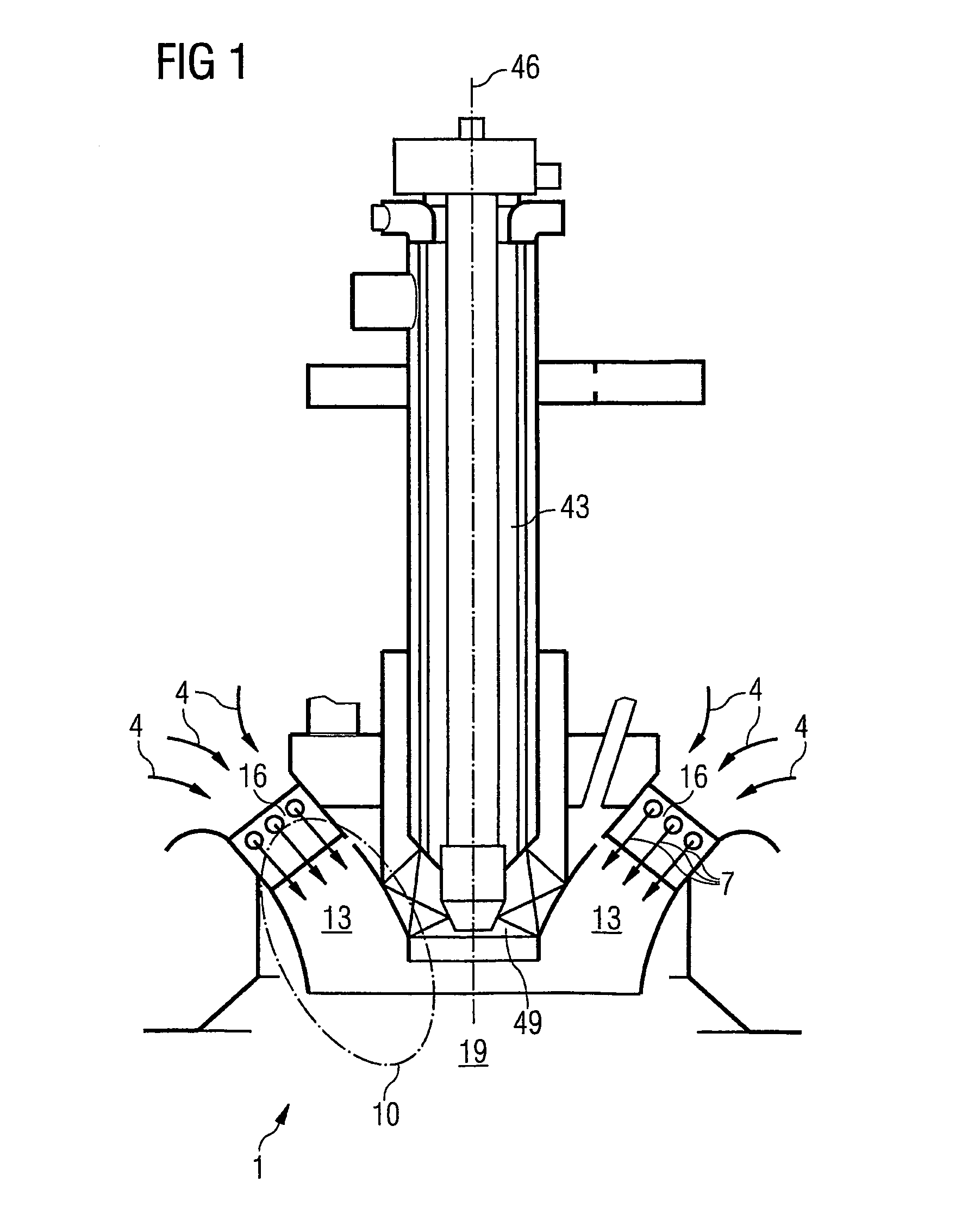
[0012]FIG. 1 shows a burner 1, in particular a premix burner 1, in particular for a gas turbine. The burner 1 has a burner longitudinal axis 46. A diffusion or pilot burner 43 is arranged for example centrally along the burner longitudinal axis 46. In premix operation the pilot burner 43 is operated to support the burner 1.

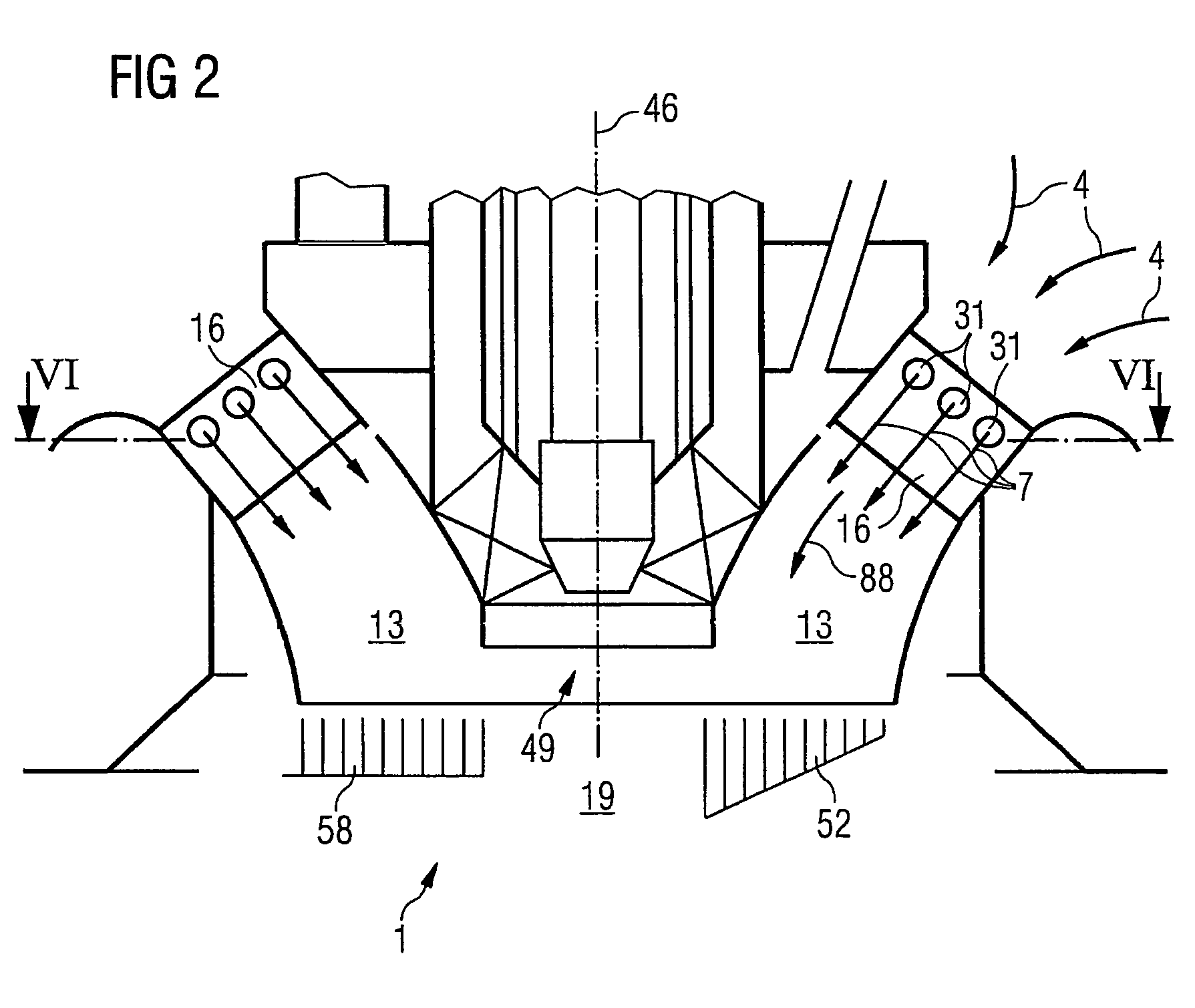
[0013]At a radial end 49 of the diffusion burner 43, fuel 7 and / or air 4 is supplied to a premix section 10 and / or a combustion chamber 19 via a channel 13 (FIG. 6) which is for example annular in shape with respect to the longitudinal axis 46. Instead of air it is also possible to supply oxygen or another gas which produces a combustible fuel-gas mixture in combination with the fuel 7.

[0014]For example, first air 4 is supplied to the channel 13 and then the fuel 7.

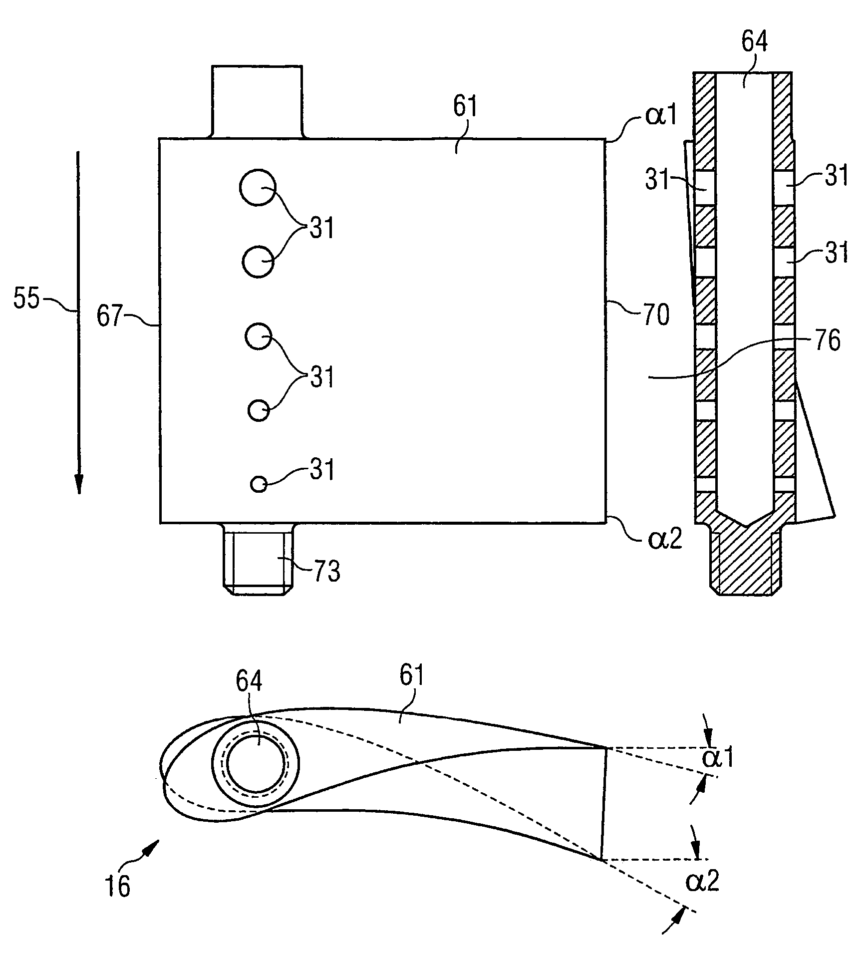
[0015]The air 4 flows in the channel 13 for example at least past one swirl blade 16, whereby the swirl blade 16 supplies for example fuel 7 to the channel 13.

[0016]The swirl blades 16 are disposed for ...


PUM


Abstract

Burners in prior art exhibit combustion instabilities in certain ranges. The operating range of burners is restricted by said instabilities. In an inventive burner, the combustible has a concentration distribution, whereby the concentration of the combustible reduces in a radial direction from the interior to the exterior.

Description

CROSS REFERENCE TO RELATED APPLICATION[0001]This application is the U.S. National Stage of International Application No. PCT / EP2003 / 009222, filed Aug. 20, 2003 and claims the benefit thereof. The International Application claims the benefits of European Patent application No. 02019530.1 EP filed Sep. 2, 2002, both of the applications are incorporated by reference herein in their entirety.FIELD OF THE INVENTION[0002]The invention relates to a burner according to the preamble clause of the independent claims.BACKGROUND OF THE INVENTION[0003]The operating range of burners with premixtures, in particular in gas turbines, is limited by self-excited combustion oscillations. Combustion instabilities of this kind can be suppressed actively, for example by increasing the power of the pilot flame, or passively, for example by means of resonators.SUMMARY OF THE INVENTION[0004]The object of the invention is therefore to demonstrate a burner in which a stable range for combustion is extended in ...

Claims


Application Information

Patent Timeline
Patent Type & Authority Patents(United States)
IPC IPC(8): F23D14/26F23D14/62F23D14/02F23R3/14F23R3/28F23R3/34
CPCF23R3/14F23R3/286F23R3/343F23R2900/00014
Inventor BERENBRINK, PETERBLOMEYER, MALTEKREBS, WERNERPRADE, BERNDSTREB, HOLGER
Owner SIEMENS ENERGY GLOBAL GMBH & CO KG
Why Eureka
Try Eureka