
Apparatus and system for well placement and reservoir characterization

a technology of apparatus and reservoir, applied in the field of subsurface exploration, can solve the problems of limiting the extent of formation geological model knowledge and estimation, and affecting measurement,

Active Publication Date: 2010-07-13
SCHLUMBERGER TECH CORP
View PDF34 Cites 52 Cited by
  • Summary
  • Abstract
  • Description
  • Claims
  • Application Information

AI Technical Summary

Benefits of technology

The modular design and advanced antenna configurations enable more accurate and robust resistivity measurements, increasing the depth of investigation and flexibility in formation model inversion, allowing for better geosteering and well placement decisions.

Problems solved by technology

The measurements are also affected by mud filtrate invasion that changes the properties of the rock near the wellbore.
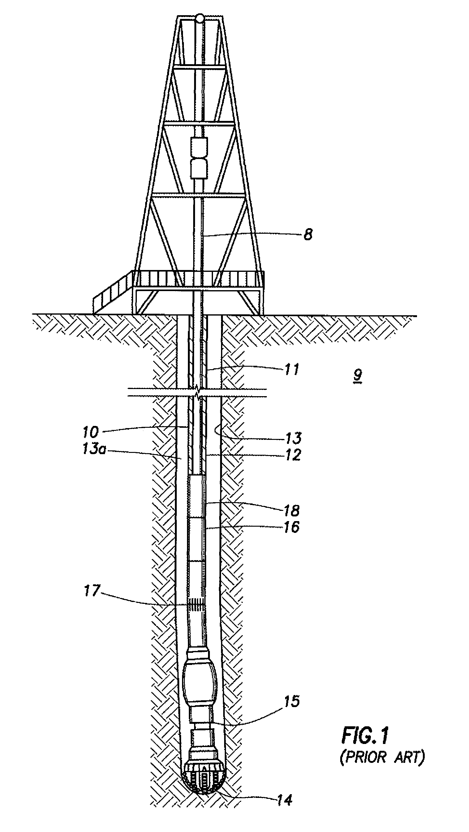
Because of the typically close placement of the resistivity sensors of a LWD tool along the drill collar relative to the transmitter, only limited radial sensitivity is attained, thereby limiting the extent of the formation geological model knowledge and estimation.

Method used


Image

  • Apparatus and system for well placement and reservoir characterization
  • Apparatus and system for well placement and reservoir characterization
  • Apparatus and system for well placement and reservoir characterization

Examples


Embodiment Construction

[0037]Embodiments of the invention relate to resistivity arrays having improved properties. Some embodiments of the invention relate to methods of using these tools in formation evaluation. Embodiments of the invention may permit inversion for more complicated formation models (i.e., formation model with more parameters) and / or may improve the robustness of resistivity measurement inversion (uncertainty reduction). Some embodiments of the invention may increase the flexibility of formation resistivity evaluation by providing more measurements, each of which may have different responses to different formation models.

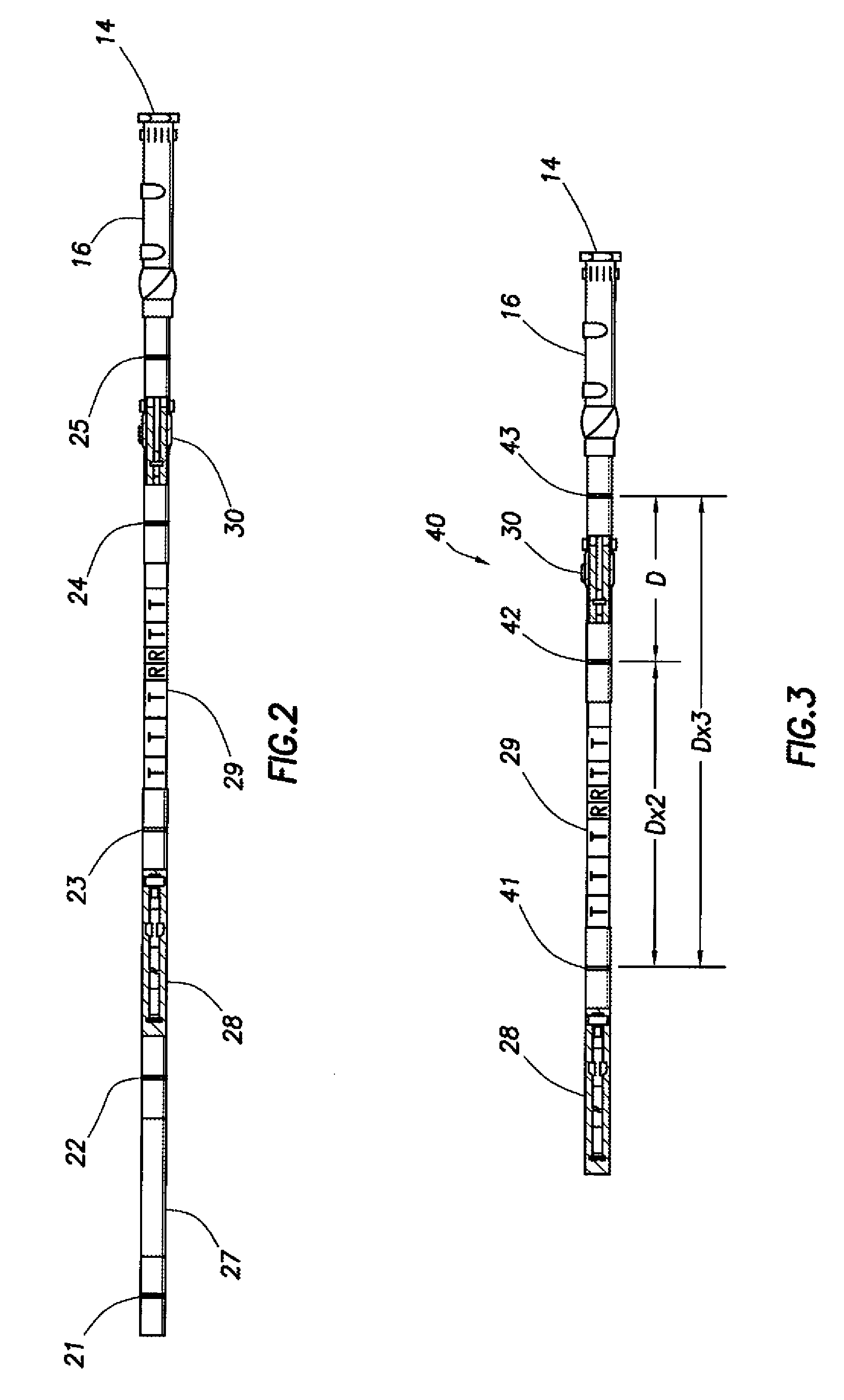
[0038]Some embodiments of the invention provide resistivity arrays having a modular design. The modular design facilitates setting up different tool configurations for different measurement requirements. For example, by extending the number of transmitter-receiver combinations (for example, one embodiment with four transmitters and one receiver, forming four transmitter-r...


PUM


Abstract

A modular downhole apparatus to determine a formation property, the apparatus being incorporated into a drill string comprising one or more downhole tools and drill pipe, the drill pipe being of the same or various lengths, the modular downhole apparatus comprising a first module having one or more antennas, wherein the first module has connectors on both ends adapted to connect with the drill string; and a second module having one or more antennas, wherein the second module has connectors on both ends adapted to connect with the drill string; wherein the first module and the second module are spaced apart on the drill string; and wherein one or more of the one or more antennas of one or both of the modules has a dipole moment that is tilted or transverse.

Description

CROSS-REFERENCE TO RELATED APPLICATIONS[0001]This CIP application claims the benefit, under 35 U.S.C. §120, of U.S. application Ser. No. 11 / 160,533, filed on Jun. 28, 2005, which claims the benefit, under 35 U.S.C. §119, of U.S. Provisional Application Ser. No. 60 / 587,689, filed on Jul. 14, 2004.BACKGROUND[0002]1. Field of the Invention[0003]This invention relates to the field of subsurface exploration and, more particularly, to techniques for determining subsurface parameters and well placement. The invention has general application to the well logging art, but the invention is particularly useful in logging while drilling (LWD), measurement-while-drilling (MWD), and directional drilling (geosteering) applications.[0004]2. Background Art[0005]Electromagnetic (EM) logging tools have been employed in the field of subsurface exploration for many years. These logging tools or instruments each have an elongated support equipped with antennas that are operable as sources (transmitters) o...

Claims


Application Information

Patent Timeline
Patent Type & Authority Patents(United States)
IPC IPC(8): G01V3/00E21BG01V3/28
CPCG01V3/28
Inventor SEYDOUX, JEANLEGENDRE, EMMANUELTAHERIAN, REZA
Owner SCHLUMBERGER TECH CORP
Learn More