Spout for ensuring evacuation of a flexible container

a flexible container and spout technology, applied in the field of flexible containers, can solve the problems of no prior art device pivoting or flexing away from the spout during filling, and none of the prior art devices provided an evacuation structur

Active Publication Date: 2010-07-20
RAPAK INC
View PDF7 Cites 19 Cited by
  • Summary
  • Abstract
  • Description
  • Claims
  • Application Information

AI Technical Summary

Benefits of technology

[0009]The present invention provides an evacuation structure for a flexible container including a spout in fluid communication with the flexible container, the spout having a base, a passageway, and an evacuation structure. The present invention provides a more efficient way of evacuating fluid from the flexible container. The evacuation structure ensures that the walls of the flexible container will not block the spout and inhibit the fluid evacuation.
[0010]In one embodiment of the present invention, the evacuation structure comprises at least one crosshair. The crosshair has two ends, and at least one end of at least one crosshair is pivotally or flexibly connected to the spout. During the filling process, the flexible connection allows fluid entering the container to pivot or flex the evacuation structure away from the spout so that the evacuation structure does not inhibit the filling of the flexible container. The fluid entering the container will physically flex the evacuation structure away from the spout.
[0015]It should also be appreciated that the evacuation structure does not have to be returned to its original position to ensure that the walls of the flexible container do not block the spout and inhibit the fluid evacuation. Rather, the evacuation structure can be adjacent to the spout during evacuation and still perform this function.

Problems solved by technology

None of the prior art devices described above provided an evacuation structure that pivots or flexes away from the spout during the filling process to allow for an unobstructed passageway for the fluid entering the container.
None of the prior art devices pivots or flexes away from the spout during filling.

Method used


Image

  • Spout for ensuring evacuation of a flexible container
  • Spout for ensuring evacuation of a flexible container

Examples


Embodiment Construction

[0022]While this invention is susceptible of embodiment in many different forms, there are shown in the drawings, and will herein be described in detail, preferred embodiments of the invention with the understanding that the present disclosure is to be considered as an exemplification of the principles of the invention and is not intended to limit the broad aspect of the invention to the embodiments illustrated.

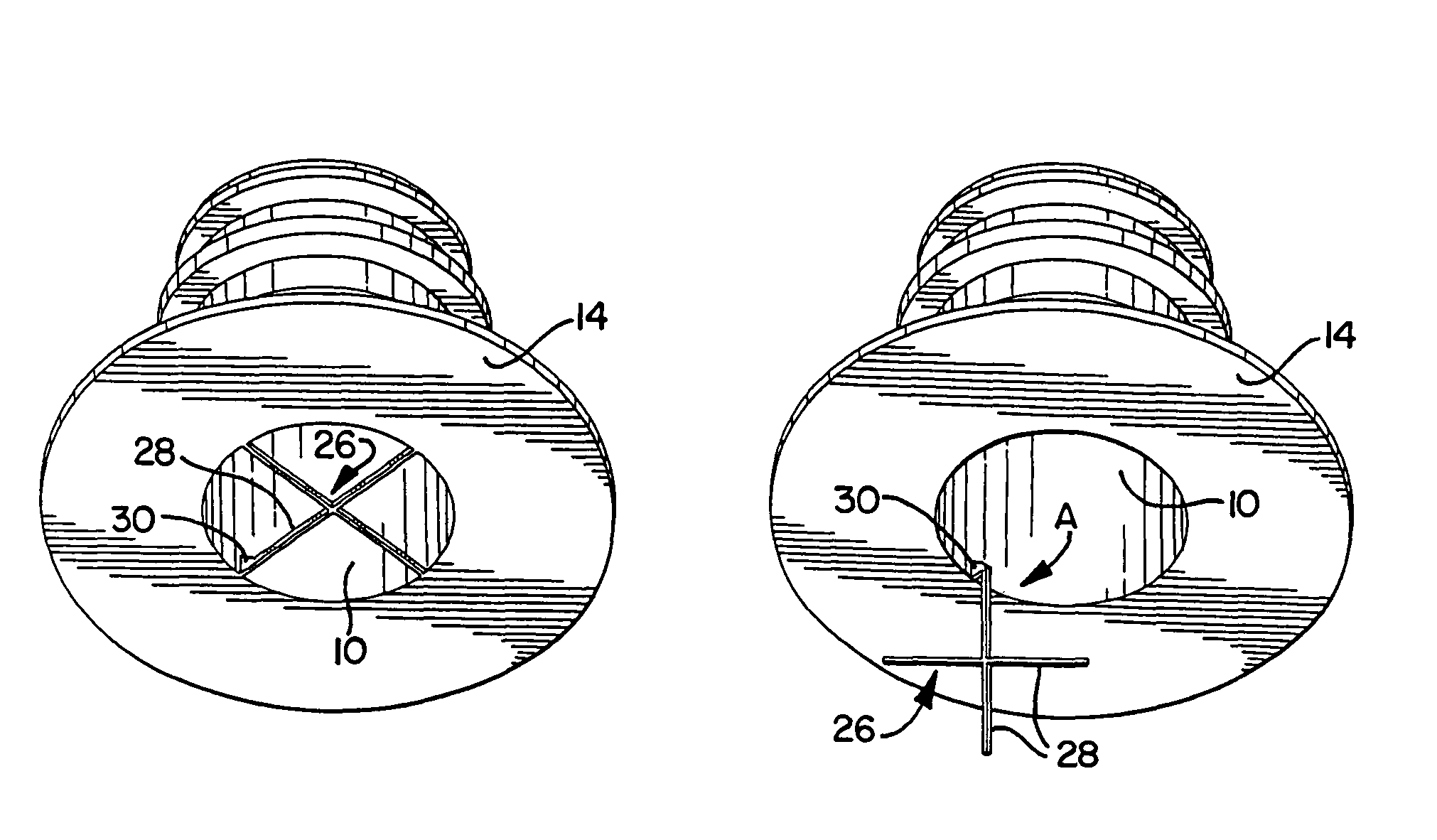
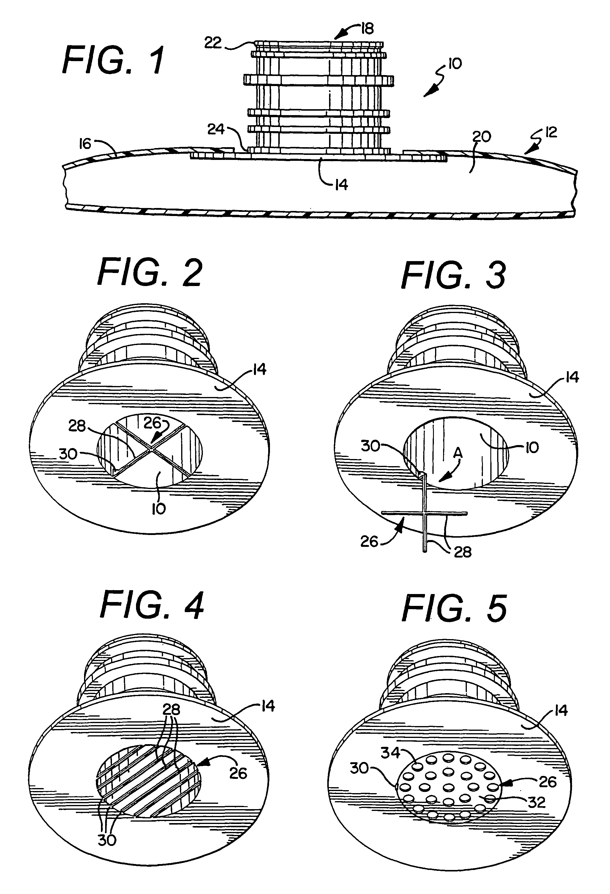
[0023]FIG. 1 shows a spout 10 in fluid communication with a flexible container 12 of the present invention. The spout 10 comprises a base 14, a passageway 18, and an evacuation structure 26. The base 14 is connected to one of a plurality of walls 16 of the flexible container 12. The spout 10 is generally centrally disposed on the base 14, the spout 10 extending in a perpendicular direction from the base 14. The passageway 18 within the spout 10 allows for fluid communication with the inside of the flexible container 20. The passageway 18 has a top end 22 and a bottom end 24. ...


PUM

PropertyMeasurementUnit
flexibleaaaaaaaaaa
diameteraaaaaaaaaa
structureaaaaaaaaaa

Abstract

The present invention is directed to a spout having an evacuation structure for a flexible container. The evacuation structure ensures that the walls of the flexible container do not block the spout of the container during evacuation of fluid from inside the container. The evacuation structure additionally pivots away from the spout during the filling of the container so that the evacuation structure does not impede the fluid entering the container during filling.

Description

BACKGROUND OF THE INVENTION[0001]This invention relates to flexible containers, and more particularly to evacuation structures for such containers. Flexible polymeric containers are well known for storing and dispensing wine, dairy products, enteral feeding solutions, fruit juices, tea and coffee concentrates, puddings, cheese sauces, and many other flowable materials, including those that must be filled aseptically. These generally include low acid materials. Flexible polymeric containers typically have walls made of polymeric films with either a monolayer or multiple layer structure. The particular polymers constituting the container film layers vary depending on the type of material to be placed in the container. The film layers may also include an oxygen barrier material layer to prevent contact between such materials and oxygen or other gas sensitive contents. The walls of the flexible containers may be metallized, or coated with a metallic layer such as aluminum to prevent inc...

Claims


Application Information

Patent Timeline
Patent Type & Authority Patents(United States)
IPC IPC(8): B65D35/00B67D3/00
CPCB65D75/5866B65D2231/001Y10S383/906
Inventor SMITH, MARK A.PETRIEKIS, DANIEL
Owner RAPAK INC
Why Eureka
Try Eureka