Multi-color holographic optical traps

a multi-functional, optical trap technology, applied in the field of three-dimensional patterns of multi-functional optical traps, can solve the problems of reducing the overall intensities, never providing precisely the phase pattern, and offering continuously varying phase profiles

Inactive Publication Date: 2010-07-20
NEW YORK UNIV
View PDF1 Cites 2 Cited by
  • Summary
  • Abstract
  • Description
  • Claims
  • Application Information

AI Technical Summary

Problems solved by technology

Practical diffractive optical elements (DOEs), however, seldom offer the requisite continuously varying phase profiles, and almost never provide precisely the phase pattern required for in a given design.
This has been recognized in the prior art as a central problem for holographic projection systems since the introduction of the kinoform.
Imperfectly imprinting the designed phase pattern onto the input beams wavefronts degrades the projected intensity patterns.

Method used


Image

  • Multi-color holographic optical traps
  • Multi-color holographic optical traps
  • Multi-color holographic optical traps

Examples


Embodiment Construction

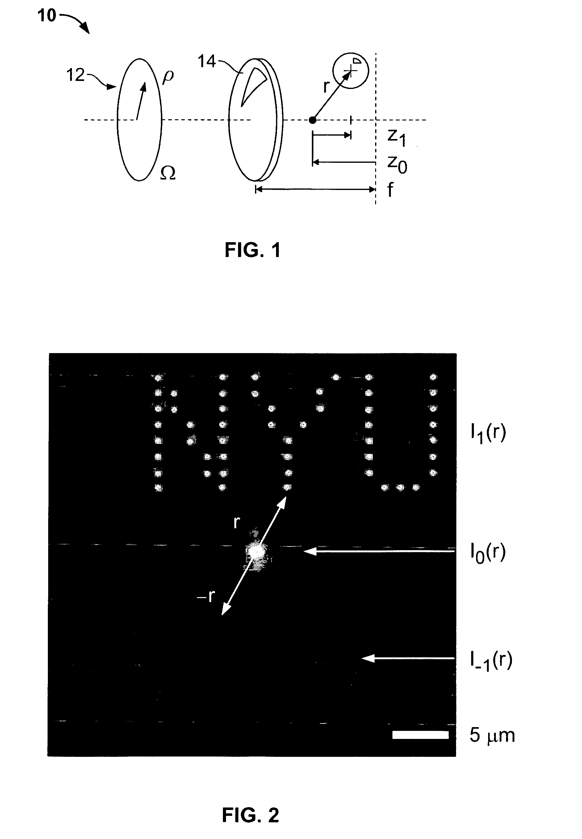
[0011]As shown in FIG. 1, a well known holographic optical trapping system 10 is powered by a collimated laser beam (not shown), which is relayed to the input pupil 12 of a high-numerical-aperture lens such as a microscope objective lens 14. This objective lens 14 focuses the laser beam to a diffraction-limited spot at a location determined by the beam's angle of incidence and degree of collimation at the lens' input pupil. Such a focused spot acts as a single-beam optical gradient force trap known as an optical trap or optical tweezer, which is capable of capturing and holding mesoscopic objects in three dimensions. Placing a wavefront-shaping hologram in a plane conjugate to the input pupil transforms the single optical tweezer into a pattern of holographic optical traps whose number, three-dimensional configuration, relative and absolute intensities, and mode structure all are encoded in the hologram. Deficiencies in the hologram's implementation might reasonably be expected to d...


PUM


Abstract

A method and system for providing multi-color holographic optical traps and patterns. The method and system employs a laser beam which interacts with a diffractive optical element with a hologram and for optics which acts to selectively pass or attenuate different light color wavelengths and to position the particular color light at selected different locations to form the different color holographic optical trap patterns and to use these patterns for various commercial purposes.

Description

[0001]This work was supported by National Science Foundation Grant Number DMR-0451589 and DBI-0233971.FIELD OF THE INVENTION[0002]The present invention relates generally to creation of three-dimensional patterns of multi-functional optical traps. More particularly the invention relates to encoding of optical traps in phase-only computer holograms that can be projected with the holographic optical trap (HOT) technique. Further, this methodology can be used to implement multi-color holographic optical tweezers with one or more holograms.BACKGROUND OF THE INVENTION[0003]Holographic optical traps use phase-only holograms to form large arrays of optical traps from a single input laser beam. By combining the beam-splitting and wavefront-shaping capabilities of computer generated holograms, holographic traps can be arranged in arbitrary three-dimensional configurations, with each trap having independently specified characteristics, including relative intensity and mode structure. The contr...

Claims


Application Information

Patent Timeline
Patent Type & Authority Patents(United States)
IPC IPC(8): G03H1/02
CPCG03H1/0005G03H1/0808G03H2001/0077G03H2001/085G03H2222/13
Inventor GRIER, DAVID G.LEE, SANG-HYUK
Owner NEW YORK UNIV
Why Eureka
Try Eureka