Power cell monitoring

a power cell and monitoring technology, applied in the direction of battery arrangement, fault location, electric vehicle, etc., can solve the problems of affecting the implementation in harsh automotive environment, and affecting the emc-performance of the device, so as to improve the power cell arrangement and reduce the voltage difference

Active Publication Date: 2010-07-20
AMI SEMICON BELGIUM
View PDF2 Cites 23 Cited by
  • Summary
  • Abstract
  • Description
  • Claims
  • Application Information

AI Technical Summary

Benefits of technology

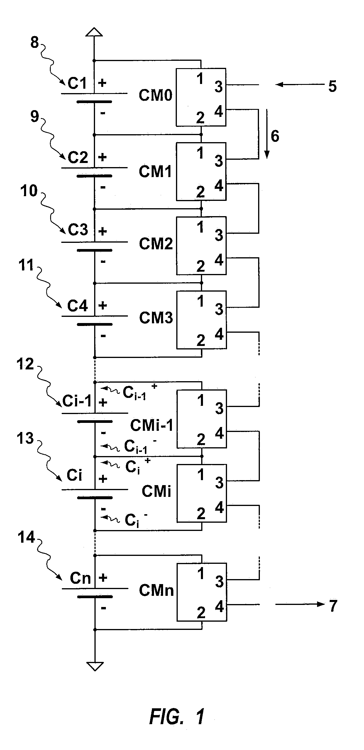
[0014]An object of the present invention is to provide improved power cell arrangements. An advantage of at least some of the embodiments of the present invention is avoiding at least one of the problems identified in the prior art. First, in some embodiments it reduces the voltage difference between two electrodes of a transistor switch involved in the transmission of data between two monitoring devices that operate at different supply voltage levels. Embodiments of the invention can allow the integration on the same semiconductor substrate of most of the components necessary for a monitoring device, digital processing circuitry and / or microprocessor and / or micro-controller and / or analog to digital and digital to analog converters, voltage and current references, amplifiers, protection circuitry protecting against e.g. electrostatic discharges, reverse polarity, voltage surges, together with one or more transistor switches involved in the transmission of data between two monitoring devices operating at different supply voltage levels.
[0016]Thirdly, embodiments of the present invention can allow the use of communication protocols that are standard communication protocols for automotive applications.
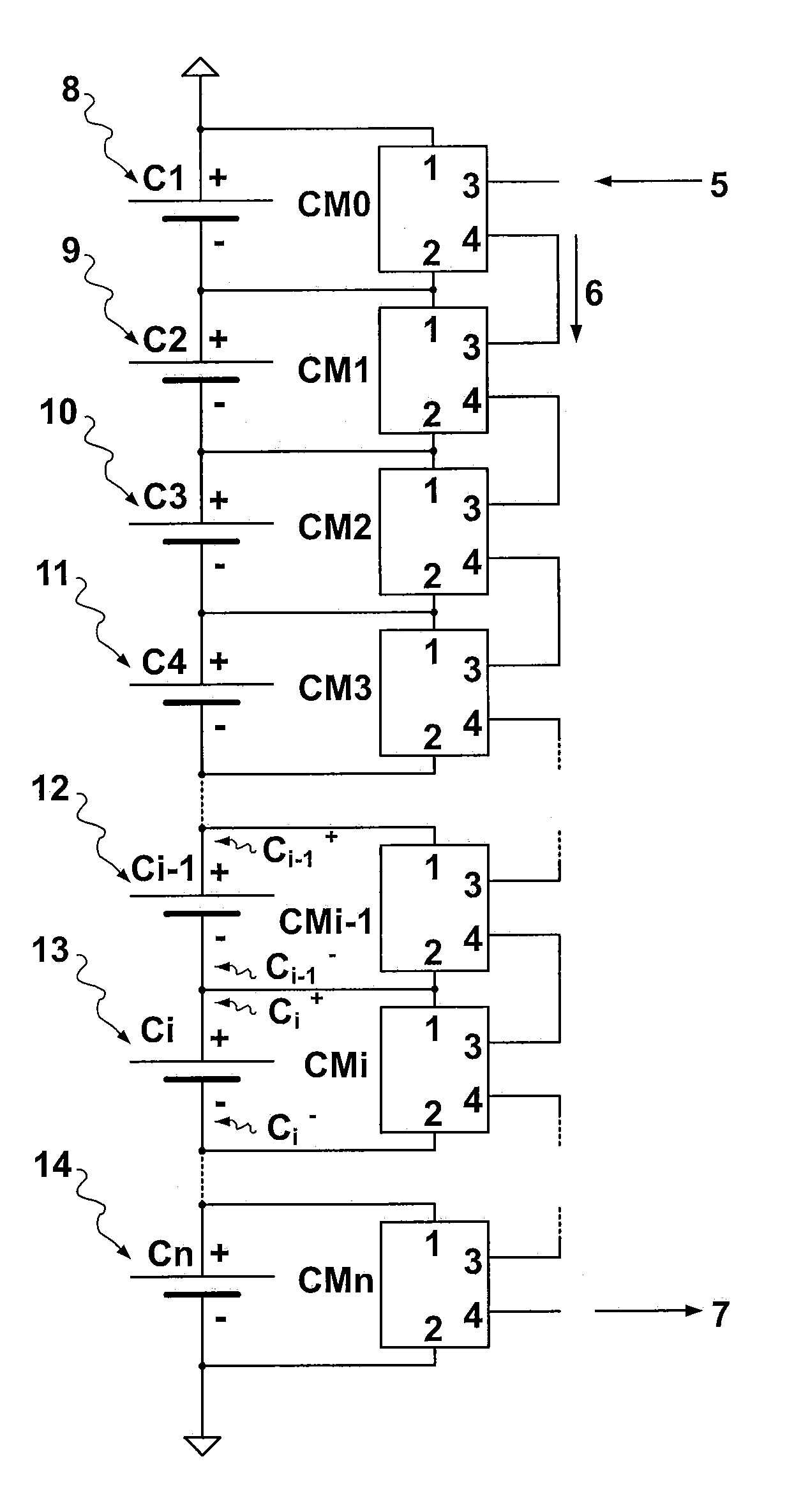
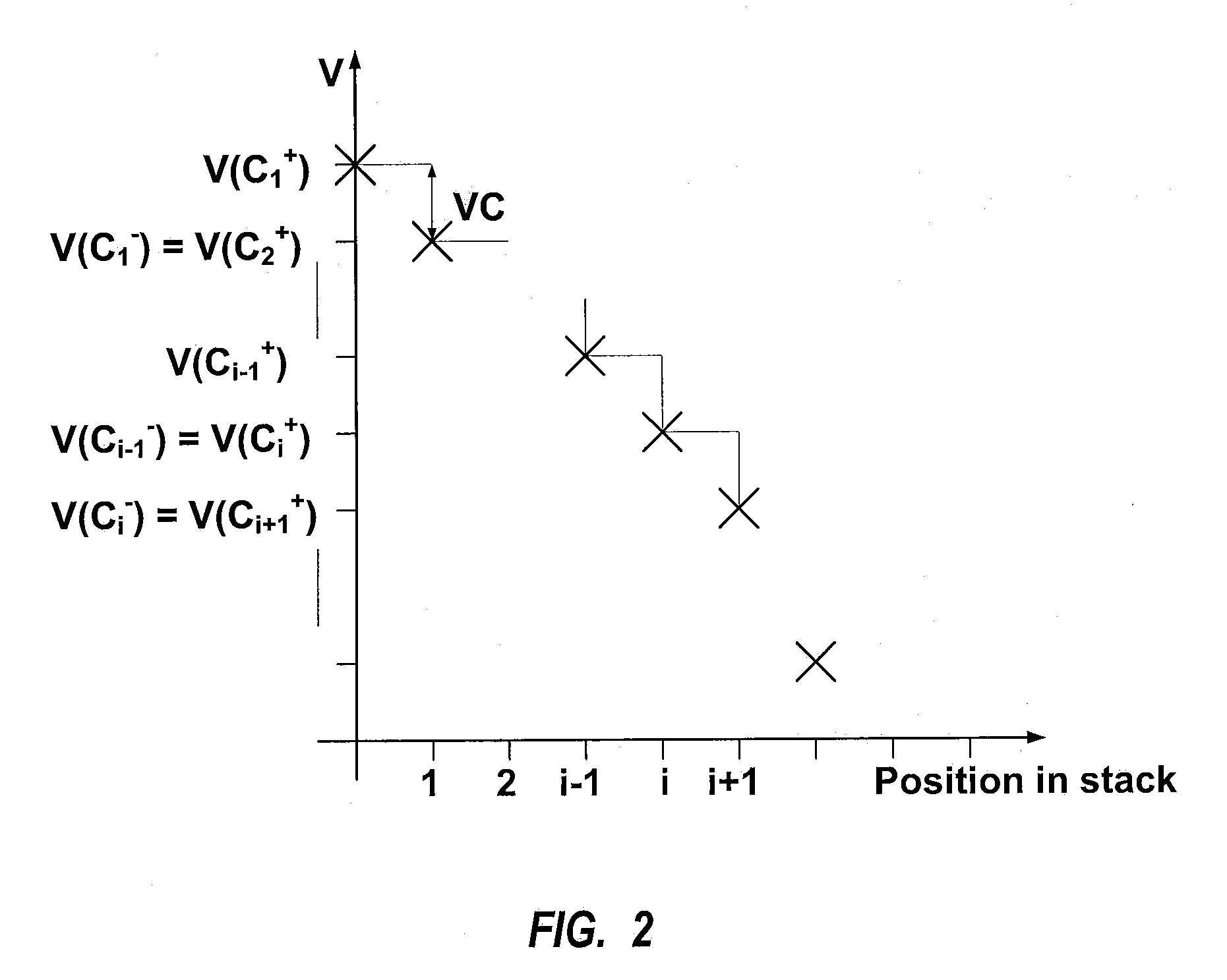
[0022]In the prior art, adjacent devices operating at different supply voltages (different reference voltages), the voltage signals generated at the output terminal (4) of a device CMi−1 and applied at the input port (3) of device CMi may be lower than the negative supply terminal of device CMi−1, imposing voltage differences (i.e. electrical stresses) higher than V(Ci−1+)−V(Ci−1−), e.g. as high as V(Ci−1+)−V(Ci−). For the invention, the voltage swing for CMi−1 at the output (4) stays in the range of V(Ci−1+)−V(Ci−1−) and this valid for all cells in the daisy chain also for cell C1 and Cn. As such, every cell within the daisy chain will have the same voltage swing at their outputs independent of their place in the chain, and as a consequence, every output (4) for of the device CMi will give exactly the same load for the power cell Ci. The present invention proposes a signaling system that allows the transmission of data between adjacent monitoring devices CMi−1 and CMi while keeping the output (4) of the monitoring devices within operating margins contrary to solutions known to the art. This part of the invention simplifies the implementation of the output and makes the signaling more robust to disturbances in the harsh automotive environment.

Problems solved by technology

The lower order control devices operating at different voltages, problems may arise when transmitting data from one lower order control device to another.
The diodes used as protection act as rectifiers and affects the EMC-performance of the device.
Such implementation is not desired in a harsh automotive environment.
When the voltage differences become important, it may become impossible to transmit messages from the first monitoring device to the second without opto-insulator.
In those cases, the integration of the micro-controller and MOSFET Q on the same silicon substrate may become difficult or even impossible depending on the integration technologies available.
While both U.S. Pat. No. 6,891,352 and WO 00 / 05596 recognize the interest of having identical lower order control devices / monitoring devices they do not propose a simple, reliable, practical and efficient method to identify the monitoring devices.
DIP switches cannot be readily integrated on the same silicon substrate as the micro-controller and MOSFET Q. DIP switches are also set manually by a human operator; hence the proposed identification system is more prone to error than if identification of the monitoring devices was done automatically by the central battery monitoring system.

Method used


Image

  • Power cell monitoring
  • Power cell monitoring
  • Power cell monitoring

Examples


Embodiment Construction

[0054]The present invention will be described with respect to particular embodiments and with reference to certain drawings but the invention is not limited thereto but only by the claims. The drawings described are only schematic and are non-limiting. In the drawings, the size of some of the elements may be exaggerated and not drawn on scale for illustrative purposes. The dimensions and the relative dimensions do not correspond to actual reductions to practice of the invention.

[0055]Moreover, the terms top, bottom, over, under and the like in the description and the claims are used for descriptive purposes and not necessarily for describing relative positions. It is to be understood that the terms so used are interchangeable under appropriate circumstances and that the embodiments of the invention described herein are capable of operation in other orientations than described or illustrated herein.

[0056]It is to be noticed that the term “comprising”, used in the claims, should not b...


PUM


Abstract

The invention relates to a signaling system for use in a system for monitoring and / or controlling a stack of power cells. The stack of power cells is series connected, i.e. the negative terminal of one power cell is connected to the positive electrode of the adjacent power cell. A monitoring device is associated with each power cell to monitor characteristics of the power cell (temperature, voltage). Every monitoring device is powered by the power cell it is associated. The monitoring device monitors the status of the cell (e.g. it measures the difference of potential between the positive terminal and the negative terminal of that cell but it may also measure the temperature of the power cell, the pH of the electrolyte if the power cell Ci is a battery, etc. and communicates information on the status of the cell to other monitoring devices. The monitoring devices are daisy chained. Data cannot be exchanged between a monitoring device from one cell and a monitoring device from another cell without that the data sent by the one device transits by the other devices in the chain.

Description

CROSS-REFERENCE TO RELATED APPLICATIONS[0001]This patent application claims the benefit of British Patent Application Serial No. 0624858.7, filed Dec. 13, 2006, which patent application is incorporated herein by reference in its entirety.DESCRIPTION[0002]The present invention relates to power cells and methods of manufacturing and operating power cells. In particular the invention relates to a signaling system and method that is applicable for use in a system for monitoring and / or controlling a stack of power cells, e.g. of a battery.DESCRIPTION OF THE RELATED ART[0003]Monitoring of individual battery elements or group of battery elements in a set of series connected batteries or series connected group of batteries is known from the art.[0004]U.S. Pat. No. 6,891,352 describes a battery apparatus for controlling battery modules connected in series, the battery apparatus to be used for electric car or hybrid electric car. So called lower order control devices control battery modules h...

Claims


Application Information

Patent Timeline
Patent Type & Authority Patents(United States)
IPC IPC(8): G08B21/00
CPCG01R31/362H02J7/0014G01R19/16542G01R31/3658G01R31/3682Y02T10/7055G01R31/396G01R31/3646G01R31/3835Y02T10/70H02J7/0013H02J7/0047
Inventor VANDENSANDE, GEERTGENTINNE, BERNARDLAULANET, FRANCOIS
Owner AMI SEMICON BELGIUM
Why Eureka
Try Eureka