Direct drive light-emitting diode (LED) driver

A technology of light-emitting diodes and light-emitting diode lamps, applied in the electronic field, can solve problems such as low loop bandwidth, low commonality, and poor loop stability, and achieve improved loop stability and loop bandwidth, reduced voltage ripple and electromagnetic interference, and high The effect of stability

Inactive Publication Date: 2012-03-21
TOP VICTORY INVESTMENTS
View PDF3 Cites 18 Cited by
  • Summary
  • Abstract
  • Description
  • Claims
  • Application Information

AI Technical Summary

Problems solved by technology

[0008] However, after the design of the direct-drive LED driver 2 for the LED light string 11 is completed, the resistance values ​​of the resistors 261-263 are fixed values, so that the output voltage Vout is not Vout, h is Vout, l, and can only be used with LED lights. The light string 11 has LED light strings with the same working voltage, and its commonality is low
In addition, the direct-drive LED driver 2 uses the error detection amplifier circuit 28 with a negative feedback structure. If the loop bandwidth is high, the loop stability will be poor; 100% of the dimming range does PWM dimming without interruption, and its dimming cannot be smooth

Method used


Image

  • Direct drive light-emitting diode (LED) driver
  • Direct drive light-emitting diode (LED) driver
  • Direct drive light-emitting diode (LED) driver

Examples


Embodiment Construction

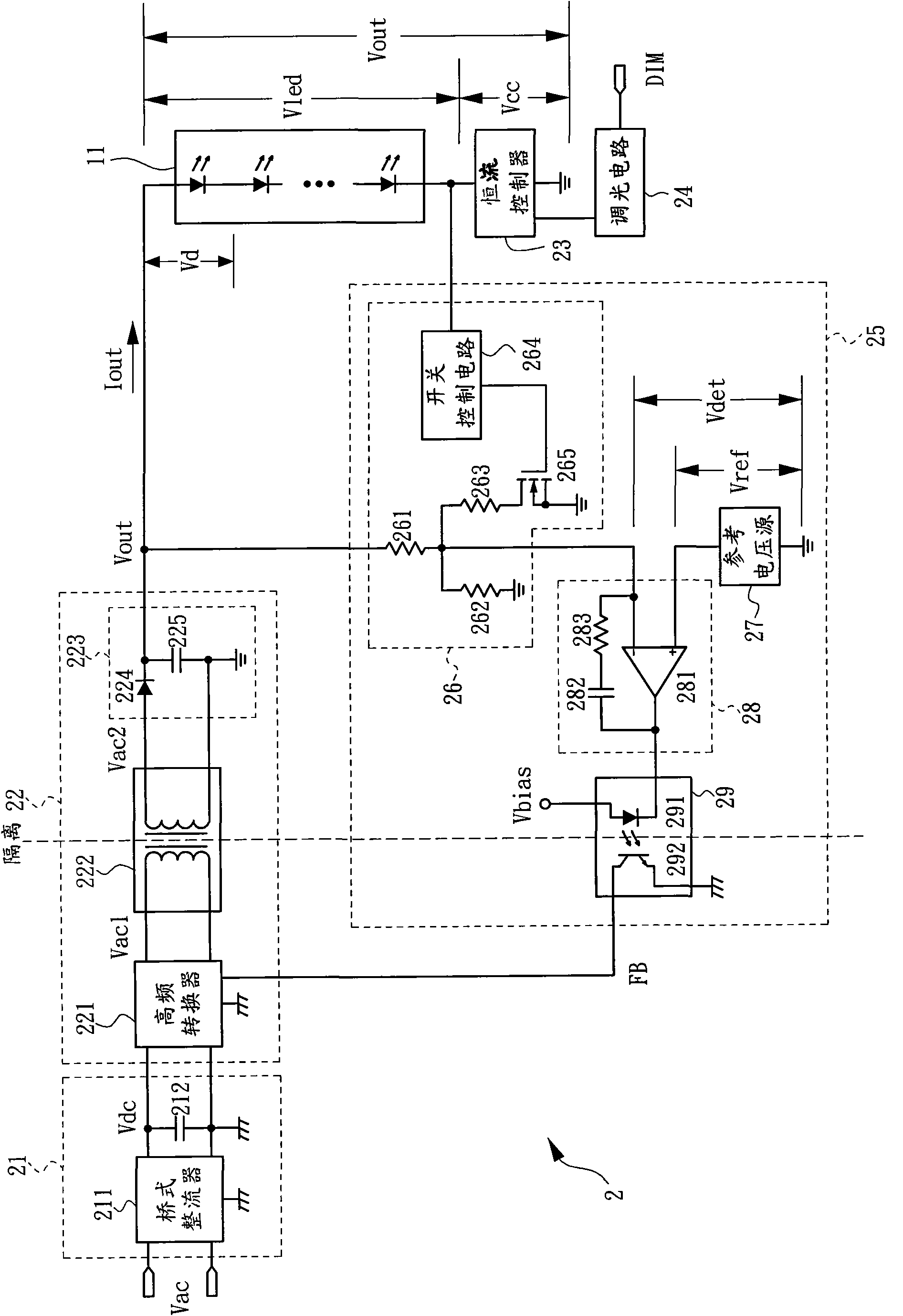
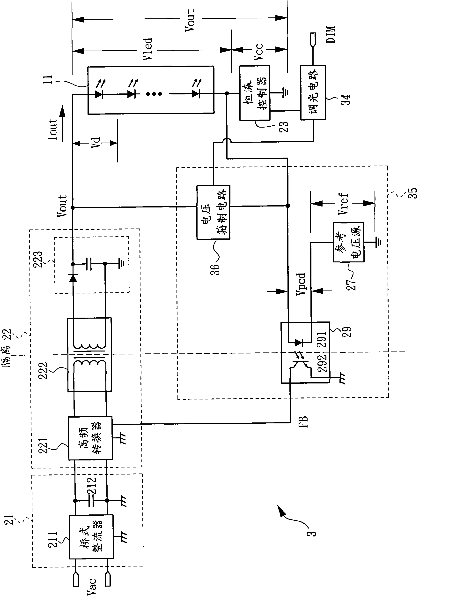
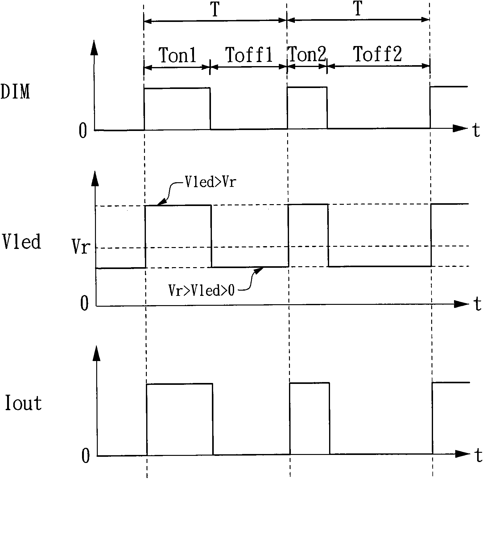
[0047] figure 2 is a circuit block diagram of the first embodiment of the direct-drive LED driver according to the present invention, image 3 for figure 2 The timing diagram of the dimming control of the direct-drive LED driver shown. See figure 2 , the LED lamp string 11 is composed of a plurality of LEDs coupled in series and has an input terminal and an output terminal. The direct drive LED driver 3 is used to receive the AC power Vac and the dimming signal DIM to drive the LED lamp string 11, wherein the dimming signal DIM is as image 3 As shown, each period T includes an enabling period and a disabling period, for example, the first period T includes an enabling period Ton1 and a disabling period Toff1, and the second period T includes an enabling period Ton2 and a disabling period Toff2, T=Ton1+Toff1=Ton2+Toff2. The direct-drive LED driver 3 includes an input rectifying filter 21, an isolated DC-to-DC converter 22, a constant current controller 23, a dimming ci...


PUM


Abstract

The invention belongs to the field of electronics and discloses a direct drive light-emitting diode (LED) driver. The driver adopts an isolation circuit to connect the output end of an LED lamp string and a constant current controller in coupling mode, output voltage of the driver changes automatically along with working voltage of the LED lamp string, and the driver can be applied to driving of the LED lamp string with various kinds of different working voltage. Accordingly, an error detection amplifying circuit in a feedback path is omitted, and stability and bandwidth of a return circuit are improved. Pulse width modulation (PWM) dimming can be conducted in a dimming range from 1% to 100% in uninterrupted mode. By means of the characteristics that when the working voltage of the LED lamp string is smaller than cut-in voltage of the LED lamp string, the current is zero, voltage difference of output voltage in an enabling period and a disabling period during PWM dimming is reduced, so that ripple voltage and electromagnetic disturbance are reduced.

Description

technical field [0001] The invention belongs to the field of electronics, and relates to a light-emitting diode (Light-Emitting Diode, LED for short) driver, and in particular to a direct-drive LED driver directly driven by an AC power source. Background technique [0002] figure 1 It is a circuit block diagram of an existing direct-drive LED driver directly driven by an AC power supply, and its output voltage adopts segmental control. See figure 1 , the LED lamp string 11 is composed of a plurality of LEDs coupled in series and has an input terminal and an output terminal. The direct drive LED driver 2 is used to receive the AC power Vac and the dimming signal DIM to drive the LED lamp string 11 . The direct drive LED driver 2 includes an input rectifying filter 21 , an isolated DC-to-DC converter 22 , a constant current controller 23 , a dimming circuit 24 and a feedback circuit 25 . [0003] The input rectifier filter 21 includes a bridge rectifier 211 and a capacitor...

Claims


Application Information

Patent Timeline
Patent Type & Authority Applications(China)
IPC IPC(8): H05B37/02
Inventor 黄金川
Owner TOP VICTORY INVESTMENTS
Why Eureka
Try Eureka