
Power conversion system and method

a technology of power conversion system and power conversion system, which is applied in the direction of electric generator control, machine/engine, greenhouse gas reduction, etc., can solve the problems of increasing the conduction loss of the power conversion system, difficult to achieve a high-power rating power conversion system, and difficult to use suitable cables and circuit breakers

Active Publication Date: 2015-02-05
GENERAL ELECTRIC CO
View PDF36 Cites 18 Cited by
  • Summary
  • Abstract
  • Description
  • Claims
  • Application Information

AI Technical Summary

Benefits of technology

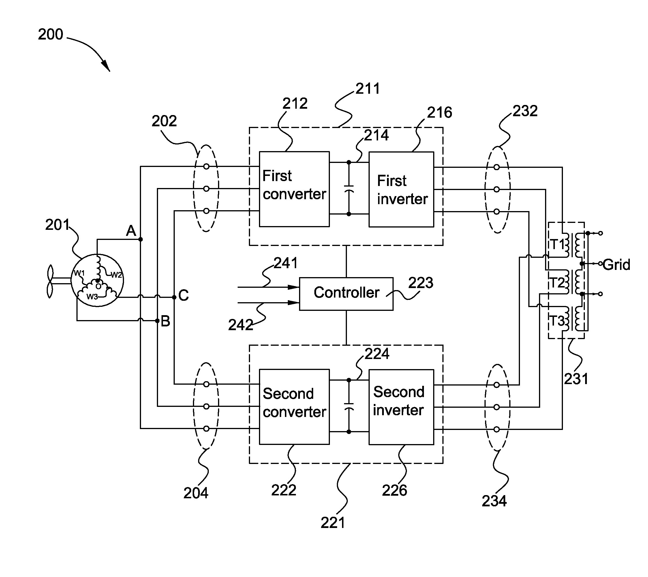
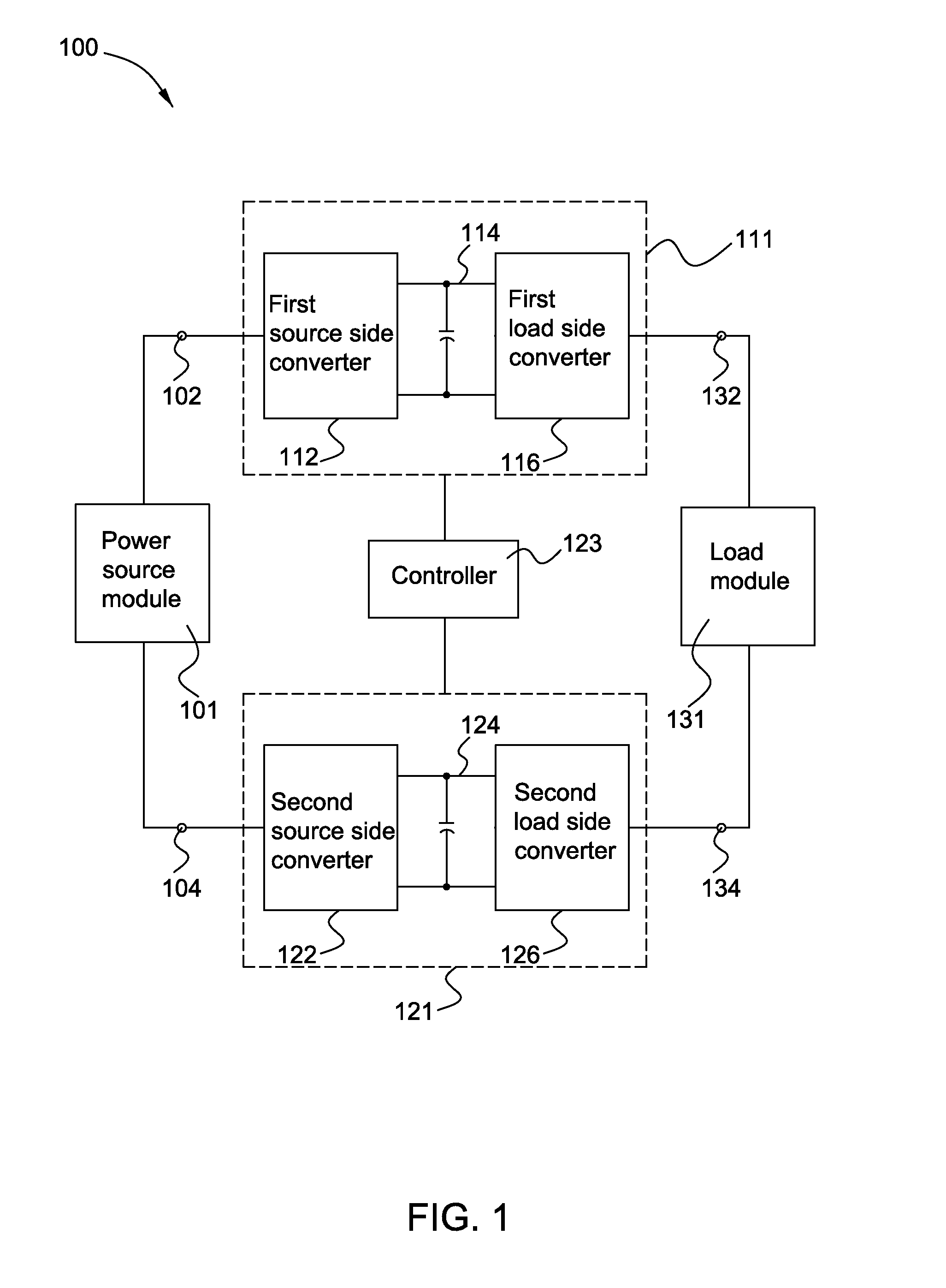
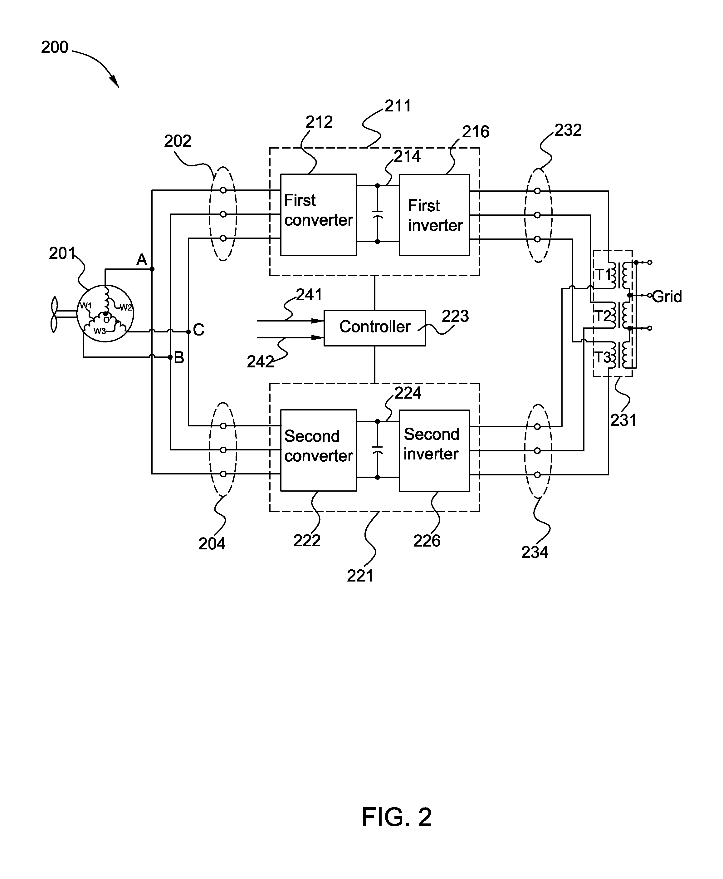
This patent relates to a system for converting wind power into electrical energy. The system includes a wind generator, two power conversion modules, and a controller. The wind generator provides input power to the first conversion module, which converts it to a first output power for delivery to a power grid. The second conversion module converts the input power into a second output power for delivery to a load module. The controller generates signals to regulate the voltage difference between the two DC links connected to the conversion modules, ensuring efficient power conversion. The technical effect of this system is improved wind power conversion efficiency and reliable electrical energy production.

Problems solved by technology

However, due to the voltage and / or current limitation of the semiconductors, it is difficult to achieve a high-power rating power conversion system.
However, by increasing the load current, the conduction loss of the power conversion system increases significantly.
Furthermore, it is difficult to use suitable cables and circuit breakers when the load current is too high.
However, conventional strategies for balancing the DC link voltages are complex.

Method used


Image

  • Power conversion system and method
  • Power conversion system and method
  • Power conversion system and method

Examples


Embodiment Construction

[0025]In an effort to provide a concise description of these embodiments, not all features of an actual implementation are described in one or more specific embodiments. It should be appreciated that in the development of any such actual implementation, as in any engineering or design project, numerous implementation-specific decisions must be made to achieve the developers' specific goals, such as compliance with system-related and business-related constraints, which may vary from one implementation to another. Moreover, it should be appreciated that such a development effort might be complex and time consuming, but would nevertheless be a routine undertaking of design, fabrication, and manufacture for those of ordinary skill having the benefit of this disclosure.

[0026]Unless defined otherwise, technical and scientific terms used herein have the same meaning as is commonly understood by one of ordinary skill in the art to which this disclosure belongs. The terms “first,”“second,” a...


PUM


Abstract

An exemplary power conversion system includes a first power conversion module, a second power conversion module, and a controller. The first power conversion module includes a first source side converter, a first load side converter, and a first DC link coupled between the first source side converter and the second load side converter. The second power conversion module includes a second source side converter, a second load side converter, and a second DC link coupled between the second source side converter and the second load side converter. The controller is configured to generate a number of switching signals according to a circuit structure of the power source module or a circuit structure of the load module. The switching signals are provided to the first power conversion module and the second power conversion module to balance a first DC link voltage and a second DC link voltage.

Description

BACKGROUND[0001]This disclosure generally relates to power conversion systems and methods for balancing at least a first DC link voltage and a second DC link voltage.[0002]For most power conversion systems, switching type semiconductors (e.g., IGBTs) are commonly used and controlled to conduct current so as to accomplish a power conversion process (e.g., DC to AC and / or AC to DC). However, due to the voltage and / or current limitation of the semiconductors, it is difficult to achieve a high-power rating power conversion system. Attempts to increase voltage rating and current conduction capability have been made to handle high power.[0003]In some power conversion systems, various new topologies are used to increase current conduction capability. For example, one topology that has been proposed is employing two or more power conversion modules with the same structure coupled in parallel in the power conversion system to increase current conduction capability. However, by increasing the...

Claims


Application Information

Patent Timeline
IPC IPC(8): H02M5/42F03D9/00H02M1/00
CPCF03D9/002H02M5/42H02J3/383H02J3/386H02J3/387H02M1/088H02M7/12H02P27/08H02M1/12H02M7/5395Y02E10/56Y02E10/76Y02E70/30H02M1/0074H02M1/0077H02M1/007
Inventor YANG, WENQIANGSHE, HONGWUNAIK, RAJENDRAIYER, SHIVKUMAR VENKATRAMAN
Owner GENERAL ELECTRIC CO
Learn More