System and method for controlling the working line position in a gas turbine engine compressor

a gas turbine engine and working line position technology, which is applied in the direction of engine control, hot gas positive displacement engine plants, jet propulsion plants, etc., can solve the problems of engine power and efficiency loss, further engine deterioration, and affecting engine performan

Inactive Publication Date: 2010-07-27
IND TURBINE COMPANY UK
View PDF35 Cites 112 Cited by
  • Summary
  • Abstract
  • Description
  • Claims
  • Application Information

AI Technical Summary

Benefits of technology

[0011]Another form of the present invention contemplates a method comprising: flowing an exhaust gas to a turbine coupled by a drive system to a low-pressure compressor and a power generation device; operating the low pressure compressor and the power generation device at a constant rotational speed; determining a surge line for the low pressure compressor; comparing the surge line with a working line for the low-pressure compressor to define a surge margin; and, actively controlling a plurality of variable inlet guide vanes within the low-pressure compressor to prevent the working line from moving towards the surge line and reducing the surge margin.

Problems solved by technology

In this prior system as the working line approaches the pressure ratio limiter the BOVs are opened which results in the engine losing power and efficiency.
Further, in this prior system the position of the VIGVs is scheduled against power and as the engine power drops the VIGVs angle closes progressively, further effecting engine performance and leading to further engine deterioration.

Method used


Image

  • System and method for controlling the working line position in a gas turbine engine compressor
  • System and method for controlling the working line position in a gas turbine engine compressor
  • System and method for controlling the working line position in a gas turbine engine compressor

Examples


Embodiment Construction

[0022]For purposes of promoting an understanding of the principles of the invention, reference will now be made to the embodiments illustrated in the drawings and specific language will be used to describe the same. It will nevertheless be understood that no limitation of the scope of the invention is thereby intended, such alterations and further modifications in the illustrated device, and such further applications of the principles of the invention as illustrated therein being contemplated as would normally occur to one skilled in the art to which the invention relates.

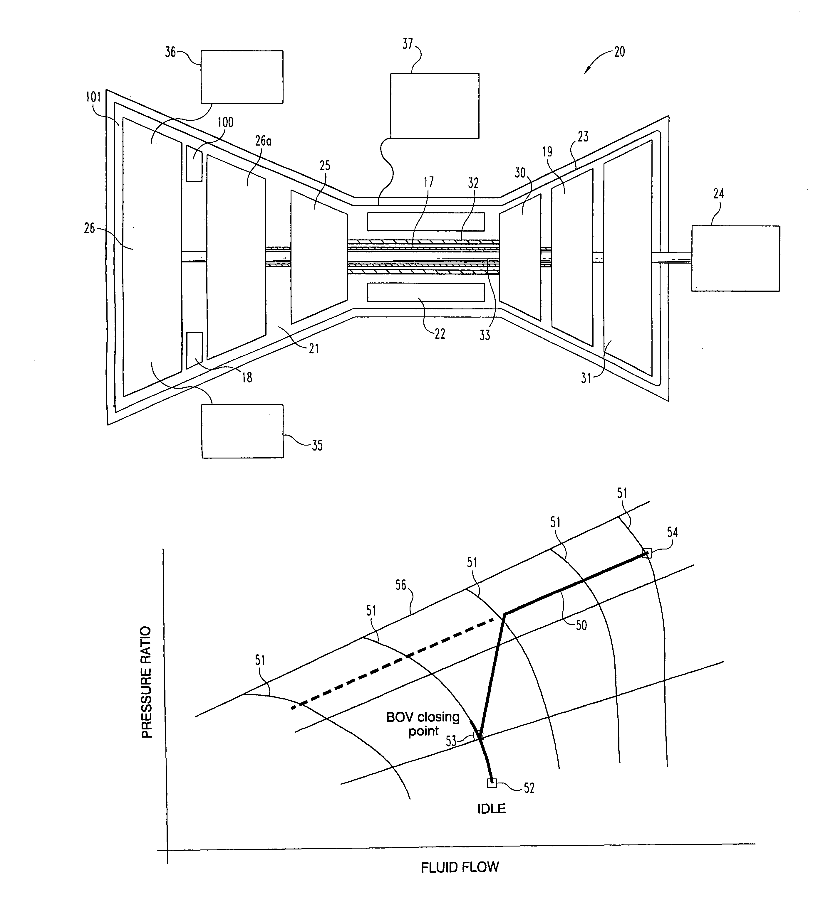
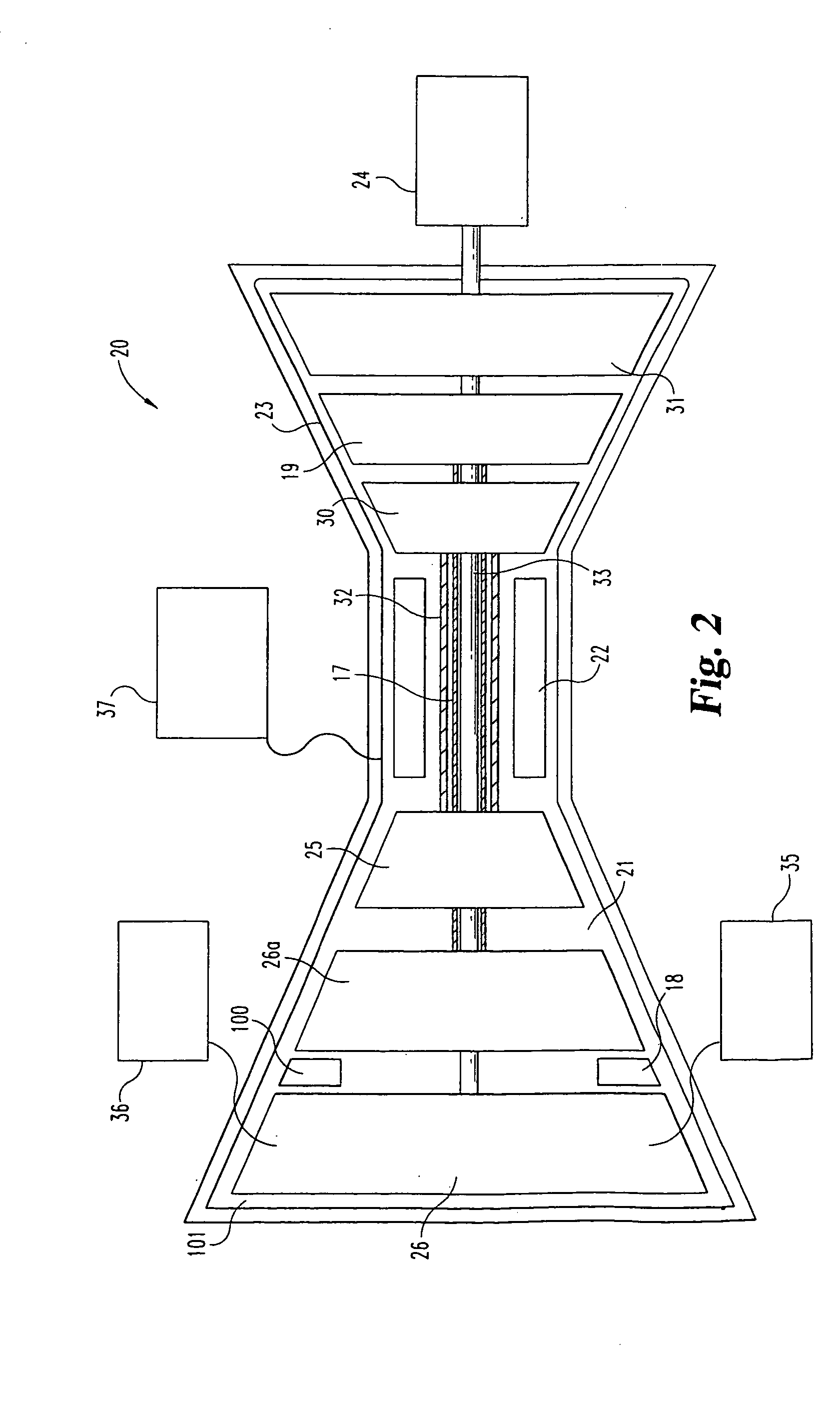
[0023]With reference to FIG. 2, these is illustrated a schematic representation of a multi-spool gas turbine engine 20. The representation is not intended to be limiting and changes in the basic engine configuration, number of stages and additional equipment is contemplated herein. The gas turbine engine 20 will be described generally; however significant details regarding general gas turbine engines will not be pr...


PUM


Abstract

A system for actively controlling the working line location within a low pressure compressor. The system includes a plurality of variable inlet guide vanes that are adjusted to maintain the working line at a constant level as the low pressure compressor rotates at a constant speed.

Description

CROSS-REFERENCE TO RELATED APPLICATIONS[0001]The present application claims the benefit of U.S. Provisional Application Ser. No. 60 / 627,399 filed on Nov. 12, 2004, which is incorporated herein by reference.BACKGROUND OF THE INVENTION[0002]The present invention relates generally to a system for controlling the operation of a gas turbine engine. More specifically, the present invention relates to the closed loop control of the working line (W / L) level of a compressor running at a constant speed through modulation of the variable inlet guide vanes (VIGV).[0003]Designers of axial flow compressors for gas turbine engines must consider many issues associated with fluid flow including stall and / or surge. A stall generally refers to a breakdown in fluid flow in only some of the stages in a multi-stage compressor and a surge generally refers to a complete breakdown of smooth fluid flow through the compressor and generally includes the reversal of flow.[0004]The air flow and pressure ratio of...

Claims


Application Information

Patent Timeline
Patent Type & Authority Patents(United States)
IPC IPC(8): F02C3/10F02C6/00
CPCF01D15/10F01D17/162F02C9/20F04D27/0246F05D2270/101
Inventor MARTIS, DANROWE, ARTHUR
Owner IND TURBINE COMPANY UK
Why Eureka
Try Eureka