Steering lock unit

a technology of steering lock and lock shaft, which is applied in the direction of mechanical control devices, instruments, anti-theft devices, etc., can solve the problems of inability to perform an operation, difficulty in achieving a balance between an operating speed and an extracting force of the lock shaft, and increased cost, so as to achieve a simple and low cost constitution and reduce the size of the steering lock unit

Inactive Publication Date: 2010-07-27
U SHIN LTD
View PDF25 Cites 7 Cited by
  • Summary
  • Abstract
  • Description
  • Claims
  • Application Information

AI Technical Summary

Benefits of technology

[0010]Thus, it is an object of the present invention to provide a steering lock unit with which it is possible to place priority on the operating speed or the extracting force of the lock member according to the engagement state of the lock member to the movable member.
[0011]It is another object of the present invention to provide a steering lock unit with which it is possible to accurately detect a lock state or an unlock state of the steering shaft with a simple and low cost construction and also possible to downsize the unit.

Problems solved by technology

The conventional power steering lock unit has only one drive system of the lock shaft, and thus it is difficult to achieve a balance between an operating speed and an extracting force of the lock shaft.
However, it is not possible to perform an operation by placing priority on any one of the operating speed and the extracting force of the lock shaft according to the engagement state.
However, this arrangement is disadvantageous because the construction becomes complicated and the cost becomes higher.
This constitutes an obstacle regarding the design for downsizing the steering lock unit.

Method used


Image

  • Steering lock unit
  • Steering lock unit
  • Steering lock unit

Examples


Embodiment Construction

[0081]An embodiment of the present invention will be described hereinafter with reference to the accompanying drawings.

[0082]In the explanation, the terms of “upper”, “lower”, “right”, “left”, “front”, “rear”, “vertical” and “lateral” will be used as a matter of convenience but do not limit the construction of the present invention.

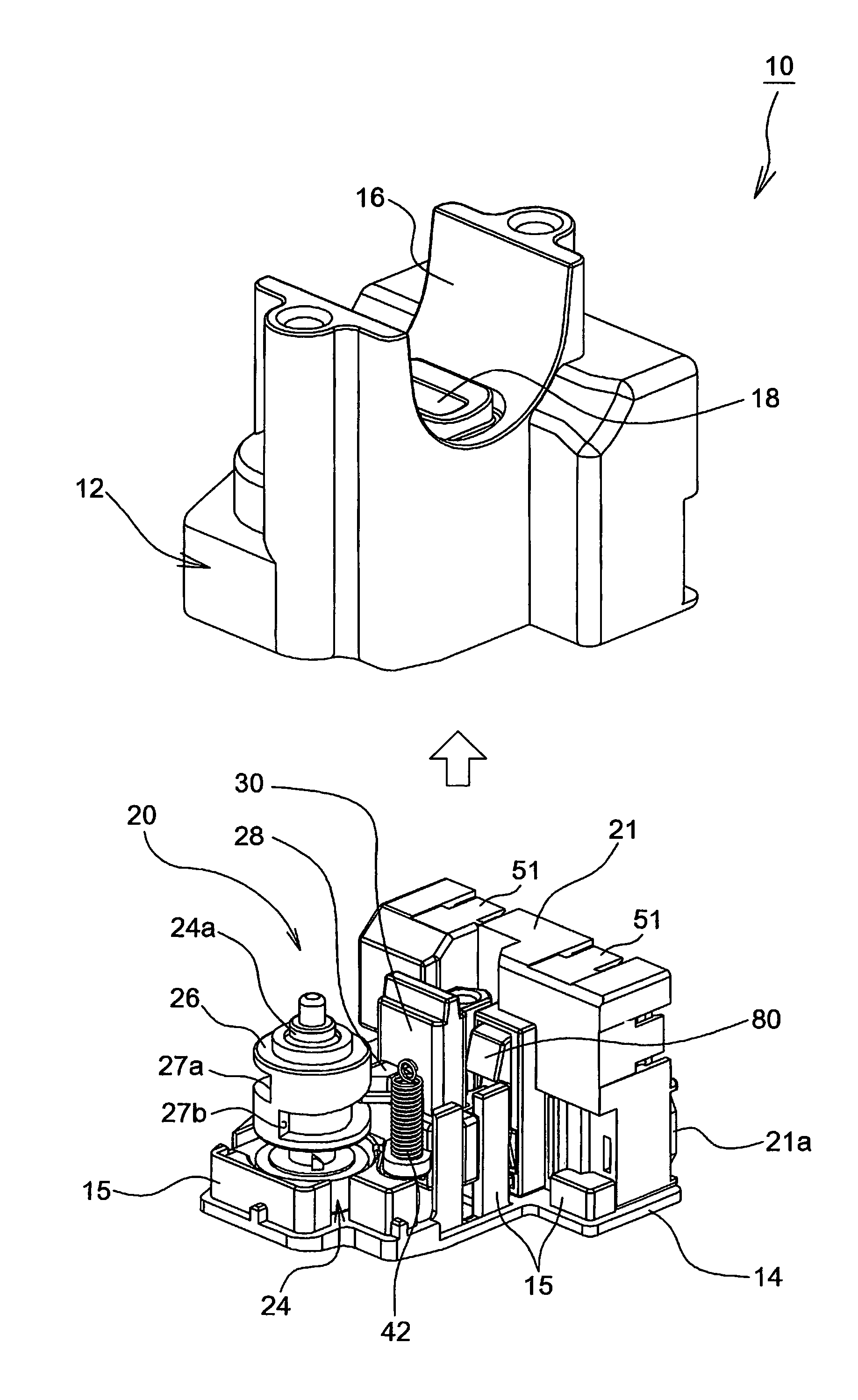
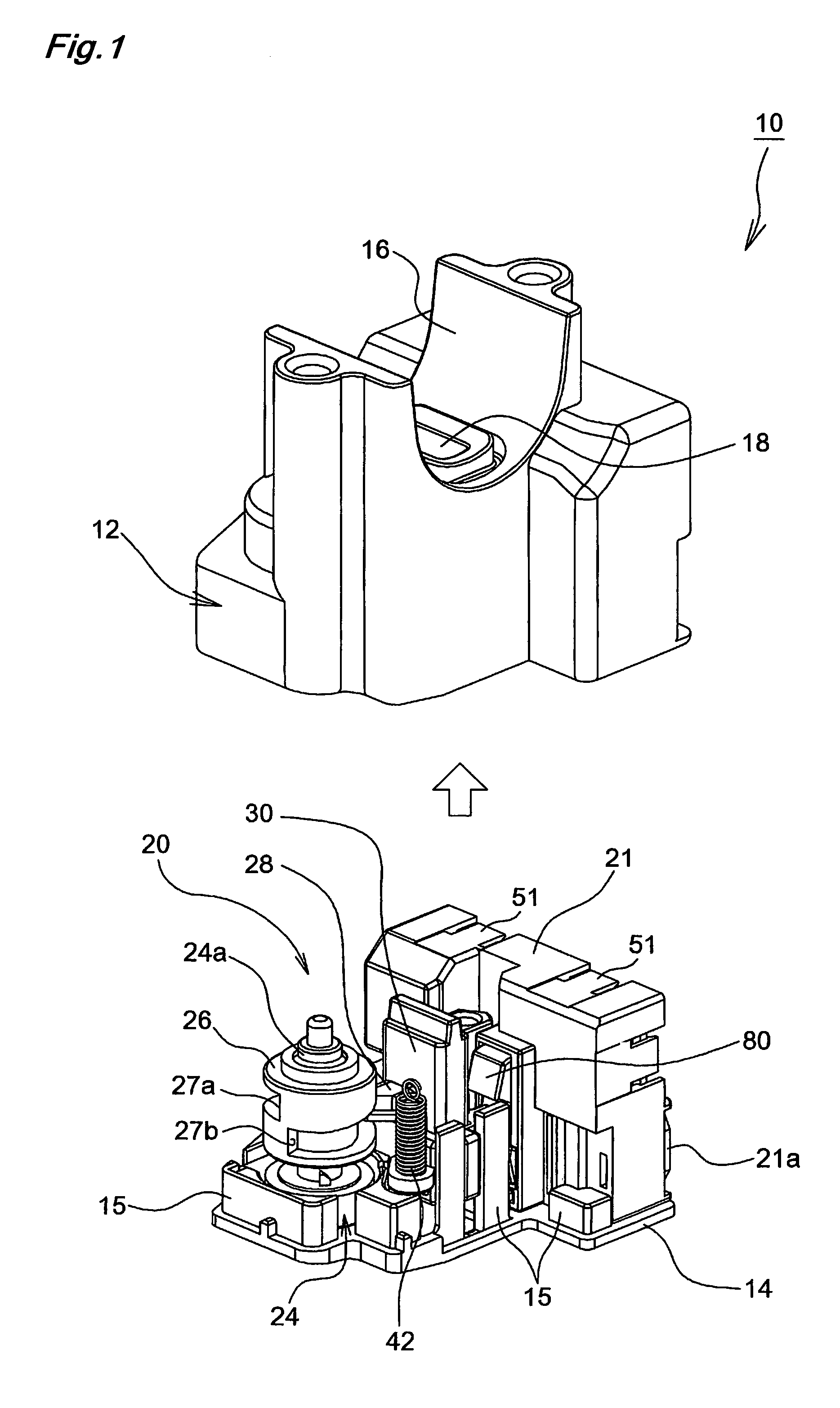
[0083]FIG. 1 shows a steering lock unit 10 of one embodiment according to the present invention with a housing 12 removed from a lid 14. The housing 12 is formed as an integral molded part made of metal or resin. The housing 12 has a lower end portion that is open and includes a housing space in its interior. On the upper end portion of the housing 12 is formed a curved surface portion 16 of substantially half cylindrical shape. On a substantially central portion is formed a lock shaft inserting hole 18 comprising, for example, a substantially rectangular opening portion.

[0084]The lid 14 also consists of an integral molded part made of metal or resin. On ...


PUM


Abstract

A steering lock unit in which it is possible to place priority on the operating speed or the extracting force of the lock member according to the engagement state of the lock member in the movable member. In a steering lock unit (10) including a transmission mechanism which transmits a power of an electric motor (22) to the lock shaft (30) which holds and releases engagement with a steering shaft. The transmission mechanism includes: a shaft portion (24a) which is adapted to rotate in response to operation of the electric motor (22); and a winder (26) which engages with the shaft portion (24a) and transmits the operation of the electric motor (22) to the lock shaft (30). When releasing the engagement of the lock shaft (30) with the steering shaft, the shaft portion (24a) and the winder (26) integrally rotate in a normal state, while the winder (26) moves in an axial direction with respect to the shaft portion (24a) in a case in which a pull-out force of the lock shaft, greater than a predetermined quantity, is necessary.

Description

BACKGROUND OF THE INVENTION[0001]1. Technical Field[0002]The present invention relates to a steering lock unit for locking a steering wheel of vehicle and so on.[0003]2. Description of the Related Art[0004]Conventionally, a steering lock unit for locking a steering wheel is employed to prevent the theft of a vehicle and so on. Typically, in the steering lock unit, when a lock shaft enters a recess formed on the outer surface of a steering shaft coupled to the steering wheel, the steering wheel becomes locked. When the shaft escapes the recess, the steering wheel becomes unlocked.[0005]The conventional power steering lock unit has only one drive system of the lock shaft, and thus it is difficult to achieve a balance between an operating speed and an extracting force of the lock shaft. For example, a steering lock unit disclosed in patent document JP2006-15984A adopts a system in which movement of a cam follower along a cam groove allows the lock shaft to move back-and-forth relative ...

Claims


Application Information

Patent Timeline
Patent Type & Authority Patents(United States)
IPC IPC(8): B60R25/02B60R25/0215
CPCB60R25/02153Y10T70/5646Y10T70/5664Y10T70/5956
Inventor TSUKAZAKI, MANABU
Owner U SHIN LTD
Why Eureka
Try Eureka